Advertisement
Quick Links
Visit www.clevelandrange.com to locate a
service or sales representative in your area.
T1 Gas Braising Pan
Installation, Operation, Maintenance, Parts & Service
This manual is updated as new information and models are released. Visit our website for the latest manual.
MODELS:
SGL-30-T1
SGL-40-T1
Read the manual thoroughly.
!
Improper installation, operation or
maintenance can cause property
damage, injury or death.
TABLE OF CONTENTS
Statement of Responsibilities . . . . . . . . . . . . . . . . . . . . . . . . . . . . . . . . . . . . . 1
For your safety . . . . . . . . . . . . . . . . . . . . . . . . . . . . . . . . . . . . . . . . . . . . . . . . . . . . 2
Installation . . . . . . . . . . . . . . . . . . . . . . . . . . . . . . . . . . . . . . . . . . . . . . . . . . . . . . . 4
Operating Instructions . . . . . . . . . . . . . . . . . . . . . . . . . . . . . . . . . . . . . . . . . . . . 6
Cleaning Instructions . . . . . . . . . . . . . . . . . . . . . . . . . . . . . . . . . . . . . . . . . . . . . 7
Preventative Maintenance . . . . . . . . . . . . . . . . . . . . . . . . . . . . . . . . . . . . . . . . 8
Trouble Shooting & Maintenance . . . . . . . . . . . . . . . . . . . . . . . . . . . . . . . . . . 9
Service Parts . . . . . . . . . . . . . . . . . . . . . . . . . . . . . . . . . . . . . . . . . . . . . . . . . . . . . 14
Part # - KE004020-2 B August 2019
For your future reference.
Model # ______________________________________
Serial # ___________ ____________________________
Model # & Serial #.
Advertisement

Related Manuals for Welbilt Cleveland T1

Summary of Contents for Welbilt Cleveland T1
-
Page 1: Table Of Contents
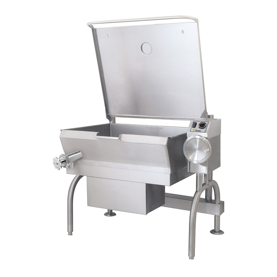
Visit www.clevelandrange.com to locate a service or sales representative in your area. T1 Gas Braising Pan Installation, Operation, Maintenance, Parts & Service This manual is updated as new information and models are released. Visit our website for the latest manual. MODELS: For your future reference. -
Page 2: Statement Of Responsibilities
STATEMENT OF RESPONSIBILITIES / DÉCLARATION DES RESPONSABILITÉS / DECLARACIÓN DE RESPONSABILIDADES This document is for use by experienced Ce document est destiné à l’usage des Este documento está destinado para el and trained Qualified Cleveland Range, Représentants de Service qualifiés et uso de los Representantes de Servicio autorisés de Cleveland Range, LLC qui calificados y autorizados de Cleveland... -
Page 3: For Your Safety
FOR YOUR SAFETY / POUR VOTRE SÉCURITÉ / PARA SU SEGURIDAD FOR YOUR SAFETY POUR VOTRE SÉCURITÉ PARA SU SEGURIDAD Do not store or use Ne pas entreposer ou No guarde ni use gasolina gasoline or any other utiliser d'essence ou o cualesquiera otros flammable liquids and d'autres liquides ou... - Page 4 WARNING / AVERTISSEMENT / ADVERTENCIA Improper installation, operation, adjustment, alteration, Do not attempt to operate this appliance during a service or maintenance can cause property damage, power failure. / N’essayez pas de faire fonctionner cet injury or death. Read the installation and operating appareil lors d'une panne de courant.
-
Page 5: Installation
INSTALLATION GENERAL Insure gas and electrical supplies match rating plate. The rating plate is located on the right side of the unit. Istallation of the unit must be accomplished by qualified installation personnel working to all applicable local and national codes. This equipment is built to comply with applicable standards for manufacturers. - Page 6 A cord and plug are supplied with the 115 volt unit. Simply plug the unit into any grounded outlet rated for a minimum ENSURE THE GAS SUPPLY MATCHES THE KETTLE'S of 10 amps. REQUIREMENTS AS STATED ON THE RATING PLATE. Standard supply voltage is 115 volts A.C., however, optional Installation must conform, with local codes or in the absence of A.C.
-
Page 7: Operating Instructions
OPERATING INSTRUCTIONS POWER TILT MANUAL OVERRIDE In case of power failure or malfunction the skillet pan can be tilted # DESCRIPTION manually following these instructions. HI / OFF / LO Switch (prior to May 2006) - Fit a 10mm SIX point socket over Power Indicator Light the Manual Tilt Shaft as shown above. -
Page 8: Cleaning Instructions
CLEANING INSTRUCTIONS DO NOT HOSE DOWN THIS AREA CARE AND CLEANING Cooking equipment must be cleaned regularly to maintain its fast, efficient cooking performance and to ensure its CLEANING INSTRUCTIONS continued safe, reliable operation. The best time to clean is shortly after each Turn unit off. -
Page 9: Preventative Maintenance
PREVENTATIVE MAINTENANCE FOR MAINTENANCE AND REPAIRS CONTACT YOUR AUTHORIZED MANITOWOC SERVICE AGENCY AND HAVE A QUALIFIED SERVICE TECHNICIAN MAINTAIN YOUR EQUIPMENT. Cleveland Range equipment requires little preventative maintenance. We do however provide the following guidelines for inspection and maintenance to keep your unit functioning at 100%. DAILY PRE-STARTUP WARNING: INSPECTION... -
Page 10: Trouble Shooting & Maintenance
TROUBLESHOOTING AND MAINTENANCE PROCEDURES The following trouble shooting guide and maintenance procedures are meant to be used by Qualified Service Technician For periodic maintenance recommendations see “Operators Manual”. SEQUENCE OF OPERATIONS If the ignition module reads a minimum of 1.0 micro- amps through the burner ground then 24 VAC is sent When using these instructions refer to the SGL-TI wiring from pins MV and MV/PV of the ignition module to pins... - Page 11 BURNER ASSEMBLY INSPECTION SKILLET PAN GASKET BURNER PAN ASSEMBLY 1. Turn unit to ON. The burner must be firing during HINGE ADJUSTMENT this procedure. INSTRUCTIONS 2. Using a stainless steel extension mirror, inspect gasket between burner pan assembly and skillet pan (sides and front only).
- Page 12 LUBRICATION SPARE PARTS LIST PROCEDURE PART NO. DESCRIPTION ....QTY. Lubricate the following parts every SK2474500 SWTCH, TILT LIMIT ....1 three months to insure smooth operation and reduce wear.
- Page 13 WIRING 110-120 VOLT, 60HZ, DIAGRAMS UL, CSA APPROVALS FUSE 3A FUSE RELAY 1 BLOWER BLOWER PILOT 220 VOLT, IGNITOR 50 HZ, CE APPROVAL PILOT IGNITOR PLUG GAS VALVE IGNITOR CABLE CONTROL MODULE CONTROL MODULE 12NC Reset Switch 11 C 24GD AIR SWITCH MVPV L/BLU...
- Page 14 WIRING 110-120 VOLT, 60HZ, DIAGRAMS UL, CSA APPROVALS FUSE 3A FUSE RELAY 1 BLOWER BLOWER PILOT 220 VOLT, IGNITOR 50 HZ, CE APPROVAL PILOT IGNITOR PLUG GAS VALVE IGNITOR CABLE CONTROL MODULE CONTROL MODULE 12NC Reset Switch 11 C 24GD AIR SWITCH MVPV L/BLU...
-
Page 15: Service Parts
SERVICE PARTS WARRANTY Our Company supports a worldwide network of Maintenance and Repair Centers. Contact your nearest Maintenance and Repair Centre for replacement parts, service, or information regarding the proper maintenance and repair of your cooking equipment. In order to preserve the various agency safety certification (UL, NSF, ASME/Ntl. Bd., etc.), only factory-supplied replacement parts should be used. The use of other than factory supplied replacement parts will void warranty. - Page 16 Page 1 of 2 FAUCETS 3/8” COPPER TUBE 1/2” Common Parts ITEM # PART # DESCRIPTION QTY. SPK ____ SINGLE PANTRY FAUCET KIT, (includes items 1-10) see page 2 for ordering information DPK ____ DOUBLE PANTRY FAUCET, (includes items 1-8 & 11) see page 2 for ordering information KE50825- ___ SPOUT , see page 2 for ordering information ____________...
- Page 17 FAUCETS Models FAUCET BRACKET SPOUT KDT12/20 ON SD TABLE SPK1 KE50825-1 DPK1 KDL60/80/100T SPK2 KE54159 KE50825-2 KEL40/60/80/100T DPK2 KE02071-1 (CP) KET20 KGT,MKET, KDP60-100/T KDL25/40T SPK3 KE54159 KE50825-3 KEL25T,KDP25/40T DPK3 KDM60/T SPK-KDM60 KE50825-2 DPK-KDM60 KDM25/40/T SPK6 KE50825-6 DPK6 KDL40/60/80TSH SPK7 KE54159 KE50825-7 KEL40/60TSH DPK7...
- Page 18 FRAME / LID ASSEMBLY TOP VIEW Open end (LID IN HORIZONTAL POSTION) of spring to be located on top. Apply removable locktite SECTION CASTER OPTION SK00393 rev. I...
- Page 19 GENERAL ASSEMBLY COMPONENTS Page 1 of 6 FAUCET 57 56 55 OPTION. ITEMS MARKED WITH * ARE NOT SHOWN. 22 100 22 23 100 DETAIL ''J'' VIEW FROM BACK OVERIDE MECHANISM CE OPTION CE OPTION DETAIL ''B'' ITEMS #122,#123 AND #125 ARE FOR CE UNIT ONLY DETAIL ''A'' DETAIL ''A''...
- Page 20 GENERAL ASSEMBLY COMPONENTS Page 2 of 6 COMMON PARTS OPTION PARTS BILL OF MATERIALS BILL OF MATERIALS SGL-40-T1 CE OPTION LP GAS KE003714-18 SGL-40-T1 CE OPTION LP GAS KE003714-18 SGL-30-T1 CE OPTION LP GAS KE003714-17 SGL-30-T1 CE OPTION LP GAS KE003714-17 SGL-40-T1 LP GAS KE003714-16...
- Page 21 GENERAL ASSEMBLY COMPONENTS Page 3 of 6 Safety Thermostat Installation Procedure (Detail A)
- Page 22 GENERAL ASSEMBLY COMPONENTS Page 4 of 6 POWER TILT MANUAL TILT OPTION SECTION C-C SECTION C-C SECTION F-F SECTION F-F DETAIL A 2 SIDES & BACK 2 SIDES & BACK NOT SHOWN NOT SHOWN 43 42 41 134 142 18 19 18 19 48 49 SECTION A-A...
- Page 23 GENERAL ASSEMBLY COMPONENTS Page 5 of 6 POWER TILT MANUAL TILT SECTION C-C SECTION C-C SECTION F-F SECTION F-F DETAIL A 2 SIDES & BACK 2 SIDES & BACK NOT SHOWN NOT SHOWN 23 24 43 42 41 134 142 18 19 48 49 SECTION A-A...
- Page 24 GENERAL ASSEMBLY COMPONENTS Page 6 of 6 O P T IO N P A R T S O P T IO N P A R T S BILL OF MATERIALS BILL OF MATERIALS KE003714-18 SGL-40-T1 CE OPTION LP GAS KE003714-18 SGL-40-T1 CE OPTION LP GAS SGL-30-T1 CE OPTION LP GAS KE003714-17...
- Page 25 CONTROL BOX ASSEMBLY WARNING: Improper installation, adjustment, alteration, service maintenance cause property CHAUD damage, injury or death. Read the installation, operating and maintenance instructions thoroughly before installing or servicing this equipment. AVERTISSEMENT: Une mauvaise installation, un réglage inadapté ou manque d'entretien peuvent occasionner...
- Page 26 SUPPORT PLATE ASSEMBLY ITEM NO. PART NO. DESCRIPTION QTY. COMMON PARTS: KE602587-1 SUPPORT PLATE ............1 KE53838-25 TRANSFORMER .
- Page 27 BURNER ASSEMBLY...
- Page 28 BURNER ASSEMBLY...
- Page 29 GAS TRAIN, TRUNNION ASSEMBLIES ITEM PART DESCRIPTION QTY. GAS TRAIN FI00134 ELBOW ..... . .2 F01518-1 SHUT OFF VALVE ....1 FI00607 NIPPLE .
- Page 30 PILOT ASSEMBLY ITEM PART DESCRIPTION QTY. SK00398-1 PILOT ASSEMBLY, NATURAL GAS ..1 SK00398-2 PILOT ASSEMBLY, LP ....1 SK2460100 GASKET ......1 SK2477000 IGNITOR/PILOT ASSEMBLY .
- Page 31 FLUE DIVERTER ASSEMBLY 24 15 18 ITEM NO. PART NO. DESCRIPTION KE002440-1 CHANNEL WLD'T ASS'Y; 30 ........1 KE002440-2 CHANNEL WLD'T ASS'Y;...
- Page 32 To learn how Welbilt Foodservice and its leading brands can equip you, visit our global web site at www.welbilt.com, then discover the regional or local resources available to you. ©2016 Welbilt Foodservice except where explicitly stated otherwise. All rights reserved. Con nuing product improvement may necessitate change of specifia ons without no ce.
Need help?
Do you have a question about the Cleveland T1 and is the answer not in the manual?
Questions and answers