Advertisement
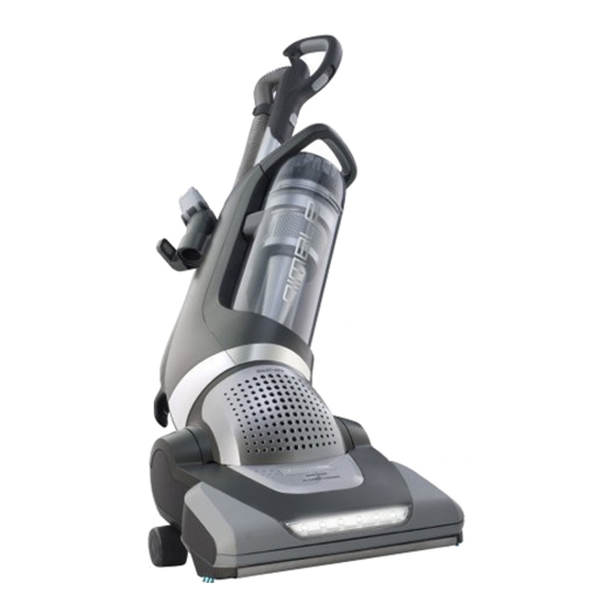
EL8600 Series Assembly / Disassembly Guide
Soleplate & Brushroll
Hood
Brushroll Motor & Drive Assembly
Front Housing
Suction Motor
Tools Required:
Saftey Glasses
Clean Pad or Soft Cloth (to prevent scratching of plastic parts during repair)
Phillips Head Screwdriver
Flathead Screwdriver
Torx-20 Screwdriver
Torx-10 Screwdriver
Table of Contents
1
Section A
Section B
Section C
Section D
Section E
Page 2
Page 3
Page 4
Page 5
Page 6
Advertisement
Table of Contents

Related Manuals for Electrolux EL8600 Series


Summary of Contents for Electrolux EL8600 Series
- Page 1 EL8600 Series Assembly / Disassembly Guide Table of Contents Soleplate & Brushroll Section A Page 2 Hood Section B Page 3 Brushroll Motor & Drive Assembly Section C Page 4 Front Housing Section D Page 5 Suction Motor Section E...
- Page 2 Note: Before any repair work is performed make sure the unit is unplugged. Note: Prior to performing any maintenance look at the RPL to become familiar with the part names and locations. Before servicing remove on-board tools, hose, and dust cup to allow easier access to ma- chine.
- Page 3 B. Hood Removal / Installation • Remove the Soleplate & Brushroll (Section A) • Using Flathead Screwdriver, pry bewteen hood and base on left side, while facing the unit, to release hood clip (Picture B.1) • Press in on front snaps to disengage from base (Picture B.2) • While pulling the handle release pedal back, lift upwards on the hood until the snap disengages from the right side (Picture B.3) • Reassemble in reverse order Picture C.1 Picture C.2 Picture C.3...
- Page 4 C. Brushroll Motor Removal / Installation • Remove the Soleplate & Brushroll (Section A) • Remove Hood (Section B) • Remove 2x T-20 screws from the Brushroll Motor Cover (Picture C.1) • Disconnect the positive and negative terminals from the motor (Picture C.2) • Remove 1x T-20 screw from the Drive Assembly (Picture C.1) • Lift the Drive assembly out of base and use flathead screwdriver to disengage the four clips which hold the cover in place (Picture C.3) • Now belt is accessible for replacement • Reassemble in reverse order Picture C.1 Picture C.2 Picture C.3...
- Page 5 D. Front Housing Assembly Removal / Installation • Remove the Dust Cup • Remove 7x T-20 screws from front housing assembly • Remove the Beauty Ring Front Fascia by carefully prying to disengage clip (Picture D.1) • Remove 2x T-20 screws holding the Beauty Ring Rear Fascia to the body (Picture D.2) • Starting where the last screws were removed work up the side where the front and rear housings join. There are clips holding the housings together that need to be disengaged before removing the front housing (Picture D.3) • You may need to use two flat head screwdrivers, putty knives, etc. to work up the seam. Pictures D.4 and D.5 show the clips in more detail • Reassemble in reverse order Picture D.1 Picture D.2 Picture D.3 Picture D.4...
- Page 6 Picture D.5 E. Suction Motor Removal / Installation • Remove the Filter Cover and HEPA filter • Remove 3x T-20 screws from beneath the HEPA filter (Picture E.1) • Remove 3x T-20 screws from front of motor housing, you will need to tilt the handle back in order to access the screws (Picture E.2) • Remove the Front Motor Cover to access the motor • Reassemble in reverse order...
Need help?
Do you have a question about the EL8600 Series and is the answer not in the manual?
Questions and answers