Advertisement
Quick Links
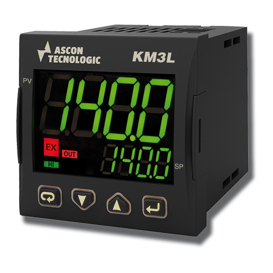
KM3L
CONTROLLER
Engineering Manual
19/06 - Code: ISTR_M_KM3L_E_00_--
Ascon Tecnologic S.r.l.
Viale Indipendenza 56, 27029 Vigevano (PV) - ITALY
Tel.: +39 0381 69871/FAX: +39 0381 698730
www.ascontecnologic.com
e-mail: info@ascontecnologic.com
1. OUTLINE DIMENSIONS (mm)
1.1 Mounting requirements
This instrument is intended for permanent installation, for
indoor use only, in an electrical panel which encloses the
rear housing, exposed terminals and wiring on the back.
Select a mounting location having the following characteristics:
1. It should be easily accessible;
2. There is minimum vibrations and no impact;
3. There are no corrosive gases;
4. There are no water or other fluids (i.e. condensation);
5. The ambient temperature is in accordance with the
operative temperature (0 to 50°C);
6. The relative humidity is in accordance with the instrument
specifications (20 to 90%);
The instrument can be mounted on panel with a maximum
thickness of 8 mm.
When the maximum front protection (IP65) is desired, the
optional gasket must be mounted.
1.2 Instrument dimensions
48
KM3L
PV
EX
OUT
PK
SP
HI
AL1 AL2
Optional
gasket
LIMIT
11
48
Panel thickness
8 mm max.
Ascon Tecnologic - KM3L - ENGINEERING MANUAL - PAG. 1
1.3 Panel Cut-out
2. CONNECTION DIAGRAM
2.1 General notes about wiring
1. Do not run input wires together with power cables.
2. External components (like zener barriers, etc.) connected
between sensor and input terminals may cause errors in
measurement due to excessive and/or not balanced line
resistance or possible leakage currents.
3. When a shielded cable is used, it should be connected at
one point only.
4. Pay attention to the line resistance; a high line resistance
may cause measurement errors.
2.2 Electrical connections
RS485
Out4: 0... 12 VDC
Analogue input
12 VDC
(note)
PV
mV, V
4... 20 mA
2 wire transmitter
12 VDC
(note)
PV
4... 20 mA
3 wire transmitter
14
65 mm min.
2.56 in min.
45
+0.6
mm
1.78
+0.023
in
Out1: 4... 20 mA or
OP1
0/2... 10 V
Limiter
output
(OP2)
OP3
OP4
(note)
Power
supply
Thermo-
mA
couple
Pt1000
Pt100
Note: Terminal 4 can be programmed as:
- 0... 12 V SSR Drive Output (OP4) connecting
the load between terminals 4 and 16;
- 12 Vdc (20 mA) transmitter power supply
connecting the 2 wire transmitter between
terminals 4 and 1; for 3 wire transmitter connect
terminal 4 to transmitter power supply input and
terminal 1 and 2 to transmitter signal output.
TERMINALS
DI1
Pin connector
1.4 mm max.
q
(0.055 in.)
L
Stripped wire
L:
5.5 mm
(0.21 in.)
Line
100...240 VDC
Neutral
Advertisement

Related Manuals for Ascon tecnologic KM3L


Summary of Contents for Ascon tecnologic KM3L
- Page 1 4... 20 mA terminal 1 and 2 to transmitter signal output. 3 wire transmitter 1.2 Instrument dimensions KM3L AL1 AL2 Panel thickness Optional 8 mm max. gasket Ascon Tecnologic - KM3L - ENGINEERING MANUAL - PAG. 1...
- Page 2 – Do not short-circuit the terminals of the SSR output. Before connecting the output actuators, we recommend to configure the parameters to suit your application (e.g.: input type, Control strategy, alarms, etc.). Ascon Tecnologic - KM3L - ENGINEERING MANUAL - PAG. 2...
- Page 3 Please, provide a T type 1A, 250 V fuse externally. 2.4.4 Output 4 (OP4) SSR Output Out4 Logic level 0: Vout < 0.5 VDC; Logic level 1: 12 V ±20%, 20 mA max.. Note: Overload protected. Ascon Tecnologic - KM3L - ENGINEERING MANUAL - PAG. 3...
- Page 4 Temperature drift: It is part of the global accuracy; Operating temperature: 0 to 50°C (32 to 122°F); Storage temperature: -30 to +70°C (-22 to +158°F); Humidity: 20 to 90% RH, not condensing. Ascon Tecnologic - KM3L - ENGINEERING MANUAL - PAG. 4...
- Page 5 3 seconds. The upper display will show PASS while the lower display shows 0. 2. Using buttons set the programmed password. Note: The factory default password for configuration parameters is 30. Ascon Tecnologic - KM3L - ENGINEERING MANUAL - PAG. 5...
- Page 6 Out-of-range, burn out and Power failure until it reaches a value of 5% higher than FSc, indicator. above which shows the Overrange message. Ascon Tecnologic - KM3L - ENGINEERING MANUAL - PAG. 6...
- Page 7 2. A “relative alarm not active at Set Point change” is an alarm that masks the alarm condition after a Set Point change until process variable reaches the alarm threshold ±hysteresis. Ascon Tecnologic - KM3L - ENGINEERING MANUAL - PAG. 7...
- Page 8 [32] AL2d time but the Note: The alarm goes ON only when the alarm condition reset is immediate. persists for a time longer than [25] AL1d time but the reset is immediate. Ascon Tecnologic - KM3L - ENGINEERING MANUAL - PAG. 8...
- Page 9 • By closing the Digital Input. LED is ON and PV is lower than SP, but inside When the the Hysteresis area, the upper display is shown in green. Ascon Tecnologic - KM3L - ENGINEERING MANUAL - PAG. 9...
- Page 10 In order to exit from configuration parameter procedure, proceed as follows: • Push button. • Push button for more than 3 s. The instru- ment returns to the “Standard display”. Ascon Tecnologic - KM3L - ENGINEERING MANUAL - PAG. 10...
- Page 11 6. OPERATIVE MODES Low limit control (B) (C) The KM3L is an FM (both FM3545 and FM3810) approved limit controller that can be configured either as a “High limit” or as a “Low limit” controller by the user. The Output 2 relay operates in fail-safe mode (relay de- energized during shutdown condition) and latching mode.
- Page 12 7. When you want to come back to the “Standard Possible problem of the calibration memory. Errt display” push the button for more than 3 s. When this error is detected, send the instrument to your supplier. Ascon Tecnologic - KM3L - ENGINEERING MANUAL - PAG. 12...
- Page 13 In the event of a faulty instrument, either within the period of warranty, or further to its expiry, please contact our sales department to obtain authorisation for sending the instrument to our company. Ascon Tecnologic - KM3L - ENGINEERING MANUAL - PAG. 13...
- Page 14 Out-of-range or burn out indicator Out 4 function P.FAL Power failure indicator bo.PF Out-of-range, burn out and Power failure indicator Output ever ON (osed as auxiliary PWS for a transmitter) Ascon Tecnologic - KM3L - ENGINEERING MANUAL - PAG. 14...
- Page 15 - For band alarm AL2H is the high alarm threshold AL2 threshold From AL2L to AL2H (E.U.) HAL2 AL2 hysteresis 1 ÷ 9999 (E.U.) AL2d AL2 delay From 0 (oFF) to 9999 (s) Ascon Tecnologic - KM3L - ENGINEERING MANUAL - PAG. 15...
- Page 16 From -1999 to (AH.P - 10) in engineering units A.L.o Adjust Low Offset -300 ÷ +300 (E.U.) A.H.P Adjust High Point From (AL.P + 10) to 9999 engineering units 999.9 A.H.o Adjust High Offset -300 ÷ +300 Ascon Tecnologic - KM3L - ENGINEERING MANUAL - PAG. 16...
Need help?
Do you have a question about the KM3L and is the answer not in the manual?
Questions and answers