Table of Contents
Advertisement
Quick Links
Advertisement
Table of Contents

Related Manuals for Ascon tecnologic AC3


Summary of Contents for Ascon tecnologic AC3
- Page 1 System User Manual User Manual M.U. Code: ISTR-MU AC3ENG01A...
- Page 2 Ascon Tecnologic Srl. Ascon Tecnologic has used the best care and effort in preparing this manual and believes that the information contained in this publication are accurate. As Ascon Tecnologic continues to improve and develop products, the information contained in this manual may also be subject to change.
-
Page 3: Table Of Contents
Technical specification ........1-1-1 AC3 System Assembly ......1-1-2 P04 Operator Panel . - Page 4 Index (continued) Chapter 3 PID, Tune and Communication ......Tuning ..........Gain Scheduling .
- Page 5 Index (continued) Chapter 6 Password and Access Control ......Description ..........Setting Access Modes .
- Page 6 Index (continued) Appendix A Resident Configurations ....... How to implement a PID controller .
- Page 7 4. When you open the package of an AC System, check all the items and verify the correspondance to the packing list below. If an item is missed or damaged, you must contact the nearest Ascon Tecnologic sales office. - AC System (P04 panel, MP-02 CPU);...
- Page 8 Current Documentation on the Internet Make sure you are always working with the latest version of this document. Ascon Tecnologic S.r.l. reserves the right to make changes to its products in the name of technological advancement. New manual revisions, when published, and can be found online at: http://www.ascontecnologic.com...
-
Page 9: Chapter 1 General Information
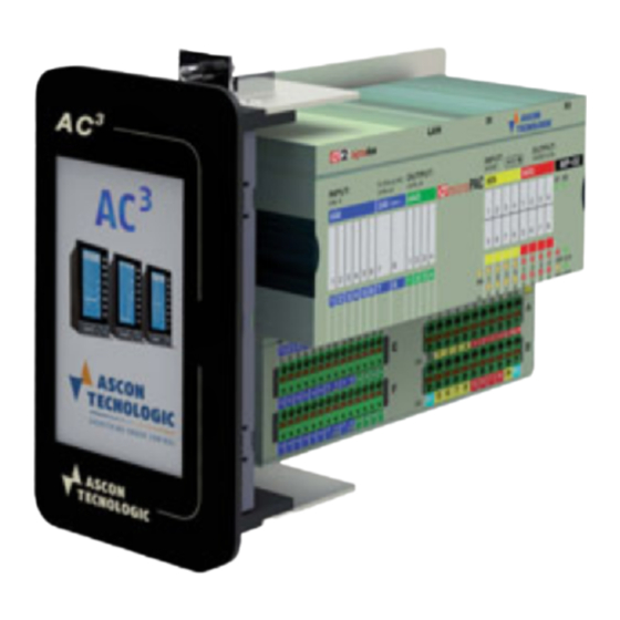
Chapter 1 General information Technical specification 1-1-1 AC3 System Assembly The AC System is composed by a P04 Touch Screen Panel device and an MP-02 Control Unit. The system, optionally, can be installed as splitted version where the P04 Panel can be installed remotely from the MP-02 Unit. -
Page 10: P04 Operator Panel
Sigmadue Solutions - AC System - User manual 1-1-2 P04 Operator Panel Display Item Description characteristics LCD type TFT display Screen dimension 4.3” Screen format 16/9 Touch-screen Resistive Resolution 480 x 272 Number of colours 262 k Back light Storage Item Description characteristics... -
Page 11: Cpu
Chapter 1 - General Information 1-1-3 MP-02 CPU Item Description specifications Processor 32 bit ARM Program memory 2 MB Flash Dynamic memory 16 MB RAM Retentive memory 64 kB redundant (32 kB + 32 kB) Memory data retention 10 years (with replaceable battery) Real Time Clock Available Timer resolution... - Page 12 Sigmadue Solutions - AC System - User manual Item Description ≤ 1°C/20°C ambient temperature 800 V between Cold junction Power supply and logics 40 Vpp between the 2 compensation Isolation channels (differential inputs) Analogue Item Description Outputs 0/2/4 optional ±10 V (±25 mA max.), 0/4... 20 mA configurable Update time 35 ms...
-
Page 13: Installation Kit
Chapter 1 - General Information 1-1-4 Installation Kit MP-02 Mounting Clamp plate Front panel adapter DIN Rail Clamp The installation kit is a mandatory item when the AC System is to be installed in place of an AC Station or Front Panels mounted. It consists of some hardware parts to allow the front panel installation: •... -
Page 14: Hardware Description
Sigmadue Solutions - AC System - User manual Hardware Description 1-2-1 P04 Operator Panel Touch Screen Panel The P04 operator panel is operated directly from the Touch Screen Area. Connections Rear and Ports 4-5 = Power supply Ethernet 24 VAC/VDC Power Supply connection The power supply is to be provided to the operator panel via terminals 4 and 5 of the terminal block. -
Page 15: Mp-02 Cpu
Chapter 1 - General Information 1-2-2 MP-02 CPU Integrated The AC system base MP-02 unit has up to 28 I/O ports: I/Os 6 AI 6 analogue inputs configurable for mA, V; 2 AI 2 optional universal or high level isolated analogue inputs configurable for: - Thermocouples (L, J, T, K, S, R, B, N, E, W3, W5);... - Page 16 Sigmadue Solutions - AC System - User manual Terminal “A” The “A” terminal block allows the connection of the +24V Power Supply, Run/Stop, 4 Digital Inputs and 4 Digital Outputs Signals. connections The terminals are positioned as follows: Label Function Run/Stop DI1 POWER Signal INPUT...
- Page 17 Chapter 1 - General Information Terminal “E” The “E” terminal block allows the connection of 6 Analogue Inputs, 2 optional Ana- logue Inputs and 4 Analogue Outputs. connections The terminals are positioned as follows: Label Function AI1 AI2 Univ. AI1 Univ.
-
Page 18: Ac3 System - Ac Station Compatibility I/O Assignment Table
Sigmadue Solutions - AC System - User manual 1-2-3 System - AC Station Compatibility I/O Assignment Table AC-Station MP-02 Meaning Terminals Terminals AI_1 1 + / 2 - E1 + / F1 - High Level Analogue Input_1 AI_2 3 + / 2 - E2 + / F2 - High Level Analogue Input_2 AI_3... -
Page 19: Diagnostic Leds
Chapter 1 - General Information 1-2-4 Diagnostic LEDs Referring to the image inserted at the previous page a description of the LEDs functions is given in the table below. LED Colour Action (note 1) Description Yellow ON RS input active (RUN program) Flickering (10Hz) Checksum error in RETAIN data Single flash CRC error in the configuration file, reset to default... -
Page 20: Communication Cables
Sigmadue Solutions - AC System - User manual X0/X1 Ports The Communications Ports electrical settings can be selected through the micros- witches located between the Serial Port connectors. DIP Switches The following table describes the selectable options. Aspect Switch Port Description Default Termination Resistance (110Ω) -
Page 21: Function Block Libraries
Chapter 1 - General Information Function Block Libraries 1-4-1 AT_AC3_Specific_Lib Description Function Block name Description This function block generates different types of alarms. It can be ALARM_ADV used also as a comparator Performs an advanced conditioning of the desired microPAC AI MP_AI_MNGT_AD value ONLY ANALOG MULTIPLEXER 2... - Page 22 Sigmadue Solutions - AC System - User manual Function Block name Description Perform the data exchange between the CPU and the touch screen front panel related to the "Loop_n Double Trend page". Note: n is an index (value 1, 2, 3 or 4) that identifies the Function Block and the loop connected.
-
Page 23: Configuration Function Block Descriptions
Chapter 1 - General Information 1-4-4 Configuration Function Block Descriptions Function Block name Description SP_PROG_RECIPE Currently not available Perform the data exchange between the CPU and the touch screen front panel, specifically related to the "Loop_n PID Configuration page" which is part of those ones accessible ONLY through the Configuration session by typing the correct password. -
Page 24: Firmware Function Blocks List
Sigmadue Solutions - AC System - User manual Function Block name Description Perform the data exchange between the CPU and the touch screen front panel related to the "1… 128 Digital Commands page" Note: n is an index (values from 1 to 8) that identifies the Digital Inputs block connected. - Page 25 Chapter 1 - General Information Function Block name Description MB_TCP_CONN_STATUS Show the status of a MBTCP/IP connection Return information of a connection identified by the IP address MB_TCP_GET_CONN_BY_ADDR of the client MB_TCP_GET_CONN_CONFIG Return configuration data of a specified active connection MEMCOPY_FROM_M Copies data from %M memory areas MEMCOPY_TO_M...
-
Page 26: At_Generic_Advanced_Lib
System - User manual 1-4-6 AT_Generic_Advanced_Lib The AT_Generic_Advanced_Lib is a function block library which includes a set of generic functionalities originally from the Ascon Tecnologic AC Station Device IEC 61131-3 Function Block Library (see the “ ” [4] manual for details). -
Page 27: At_Process_Generic_Lib
Chapter 1 - General Information 1-4-7 AT_Process_Generic_Lib The AT_Process_Generic_Lib is a function block library which contains a set of generic process function blocks useful for the IEC 61131 programming. The table here reported gives the complete list of the function blocks. Function Block name Description AICOND_ADV... -
Page 28: At_Communications_Lib
Sigmadue Solutions - AC System - User manual 1-4-9 AT_Communications_Lib The AT_Communications_Lib allows a simplified access to the communication IEC 61131-3 Function Block Library functions of MP-02 CPU (see the “ ” [4] manual for details). Follows the complete list of the function blocks available with the library: Function Block name Description COMMS_MNGT_MP0x... -
Page 29: Startup
Chapter 2 Startup STARTUP PROCEDURE The flowchart lists steps you must carry out to have your AC³ system installed on the plant and properly controlling the Customer process. Unpack and check the instrument Install, connect and wire Power ON the system Standard Standard Custom... -
Page 30: Keyboard
Sigmadue Solutions - AC System - User manual Keyboard Customized Page Loop 1 Loop 2 1234.56 1234.56 1234.56 1234.56 -1234.5 -1234.5 Auto Auto Loop 3 Loop 4 1234.56 1234.56 cmd1 1234.56 1234.56 cmd2 -1234.5 -1234.5 cmd3 Auto Auto cmd4 The display has touch screen functionalities and is programmed to have many dif- ferent areas with specific functions. -
Page 31: Display
Chapter 2 - Startup Display The display panel is based on a graphic 4.3" TFT LCD 262 k-colours 272 x 480 pixels high resolution touch screen display. The AC³ system is able to display several types of page panels specifically designed to manage all the functionalities developed into the control strategy. - Page 32 Sigmadue Solutions - AC System - User manual For a detailed description of the above please refer to the “Appendix A” of this manual. Custom Page: Front panel to manage up to four loops with numeric indications of Process Variable, Working Set Point and Output Value. The panel enables the user to submit commands for each loop (Auto/Man, Local/ Remote, etc.) and also submit general commands (cmd1...
-
Page 33: Custom
Chapter 2 - Startup 2-2-1 Custom Page Panel Customized Page Loop 1 Loop 2 1234.56 1234.56 1234.56 1234.56 -1234.5 -1234.5 Auto Auto Loop 3 Loop 4 1234.56 1234.56 cmd1 1234.56 1234.56 cmd2 -1234.5 -1234.5 cmd3 Auto Auto cmd4 This page displays main parameters, commands and status of up to 4 controllers. The Process Variable, Working Set Point and Control Output values are numeri- cally represented whilst Auto/Man and Loc/Rem commands can be performed through the dedicated buttons. - Page 34 Sigmadue Solutions - AC System - User manual can notify to the system that the loop must be forced to a specific functioning mode. Possible modes are: AUTO (Automatic) written in black on white field or MAN (Manual) written in black on red field. 8.
-
Page 35: Four Bargraph Panel
Chapter 2 - Startup 2-2-2 Four Bargraph Panel Four Bargraphs 1234.56 kg/h SPL_L2 -1234.56 WSP_L2 -1234.56 Loop1 Loop2 Loop3 Loop4 Auto Auto Auto Auto -123.4 -123.4 -123.4 -123.4 This display type is less rich of information than the previous one; because it lacks the output bargraph and the main variable engineering units, but surely, it is the most versatile;... - Page 36 Sigmadue Solutions - AC System - User manual 7. Local/Remote Set Point Selection Button Set Point operating mode button of the selected loop (Loop 2 in the example). Pressing with a finger on this area, the system toggles the Set Point of the selected loop from the Loc (Local) to the Rem (Remote) one.
-
Page 37: Two Bargraph Panel
Chapter 2 - Startup 2-2-3 Two Bargraph Panel Two Bargraphs 1234.56 kg/h SPLoc 1234.56 1234.56 1234.56 Auto 1234.56 1234.56 -123.4 The main purpose of this display is to provide the front panel for those applications were two PID loops are typically required, such as a cascade control loop (Master and Slave). - Page 38 Sigmadue Solutions - AC System - User manual 6. Scrolled Variable Value This field is used first to show/edit the SPLoc1/SPLoc2 or SPLoc3/SPLoc4 value. Then, by pressing the circulating button, it can show up to 5 more generic numeric values (AI1, AI2, AI3, AI4 and AI5). It consists of 6 numbers with sign and decimals (default 4 integers and 2 decimals).
-
Page 39: One Bargraph Panel
Chapter 2 - Startup 2-2-4 One Bargraph Panel One Bargraph 1234.56 kg/h SPLoc 1234.56 1234.56 Auto 1234.56 -123.4 1. Alarm Banner This area is used by the system to display the active alarms. The messages scroll on the banner, from the right to the left, in order to warn the user about the active alarm conditions. - Page 40 Sigmadue Solutions - AC System - User manual 10. Set Point Slider indicator Graphical representation, through a red arrow slider, of the real time SP value. 11. Digital Inputs Status These fields can be used to display up to 4 digital status conditions such as alarms or simple logic status.
-
Page 41: Double Trend Panel
Chapter 2 - Startup 2-2-5 Double Trend Panel Two Trend 1234.56 kg/h SPLoc 1234.56 5 min 1234.56 Auto 1234.56 -123.4 This display has almost the same functionality of the 2 Bar Panel module, with the addition of a trend chart of an analogue variable. Its main purpose is to provide the front panel of a simple control loop. - Page 42 Sigmadue Solutions - AC System - User manual 7. Time Scale Numerical display of the time span of the trend chart. The user defines this value by choosing between the following set: 1, 2, 5, 10, 30 min. - 1, 2, 5 hours. 8.
-
Page 43: Alarm & Status Panel
Chapter 2 - Startup 2-2-6 Alarm & Status Panel Alarm & Status Description Alarm line Description Alarm line Description Alarm line Description Alarm line Description Alarm line Description Alarm line Description Alarm line Description Status line Description Alarm line Description Alarm line Description Status line Description Status line Description Alarm line... -
Page 44: Display Numericals Panel
Sigmadue Solutions - AC System - User manual 2-2-7 Display Numericals Panel Display Numerics Description line 1234.56 eng.un Description line 1234.56 eng.un Description line 1234.56 eng.un Description line 1234.56 eng.un Description line 1234.56 eng.un Description line eng.un 1234.56 Description line 1234.56 eng.un Description line... -
Page 45: Edit Numericals Panel
Chapter 2 - Startup 2-2-8 Edit Numericals Panel Numerical Parameters Description line 1234.56 eng.un Description line eng.un 1234.56 Description line 1234.56 eng.un Description line eng.un 1234.56 Description line 1234.56 eng.un Description line eng.un 1234.56 Description line 1234.56 eng.un Description line eng.un 1234.56 Description line... -
Page 46: Edit Digitals Panel
Sigmadue Solutions - AC System - User manual 2-2-9 Edit Digitals Panel Digital Parameters Text_Field Text_Field Text_Field Text_Field Text_Field Text_Field Text_Field Text_Field Text_Field Text_Field Text_Field Text_Field Text_Field Text_Field Text_Field Text_Field This display provides the functionality of a control panel for digital commands. It has 16 outputs, that are driven all together, by the pattern selected through one of the 3 supported selection modes: Keyboard, Supervisory Computer and the 4 Dig- ital Inputs. -
Page 47: 2-2-10 Sp Prog. Mngt Panel
Chapter 2 - Startup 2-2-10 SP Prog. Mngt Panel xxxxxxxxxx 1234.56 kg/h SPLoc 1234.56 5 min 1234.56 Stop Next Reset Auto 1234.56 -123.4 This display provides a suitable interface to the Set Point programmer module, available on the AC30 controller, only. It provides both the trend of 2 variables and the status displays and the user commands to the Set Point programmer. - Page 48 Sigmadue Solutions - AC System - User manual Trend of CI1 Recent trend curve display of the analogue input signal CI1. 8. Working Set Point Cursor XXXXXXXXXXXXX. 9. Time scale Numerical display of the time span of the trend chart. 10.
-
Page 49: Select A Resident Strategy
Chapter 2 - Startup 22. Operative keys Using these keys the user can easily move through the instrument pages. The command are: Back page, Config, Circle, Next page. Select a resident Strategy At power up, the AC³ system can either show on the display the first panel of the selected downloaded strategy or the "Cannot read Operative Page Variable. - Page 50 Sigmadue Solutions - AC System - User manual...
-
Page 51: Pid, Tune And Communication
Chapter 3 PID, Tune and Communication Tuning The Tuning method used in the AC³ systems is a highly sophisticated new generation algorithm which represents conceptually the "state of the art" in his context. Basically, the method on which is based can be represented like follows. Hysteresis relay G(s) Tune active... - Page 52 Sigmadue Solutions - AC System - User manual In case of need to execute an Auto - Tuning function, from a whatever operational page, the steps to be followed are: Double trend 1234.56 kg/h 00000 99999 SPLoc 1234.56 Password valid. 5 min 1234.56 Enter...
-
Page 53: Gain Scheduling
Chapter 3 - PID, Tune and Communication Gain Scheduling Gain scheduling is based on the technique of changing the value of the 3 terms parameters of the PID algorithm accordingly to a desired logic such as the value of whatever variable (like the SP or the PV variable), the controlled variable and/or other process signals. -
Page 54: Two Freedom Degrees Pid
Sigmadue Solutions - AC System - User manual Two freedom degrees PID In order to provide very effective control capabilities, the AC³ systems are supplied with a PID algorithm with two degree of freedom. This second degree corresponds to the O.C. parameter (Overshoot Control) that provides a sort of SP Weighting which determines the error then used by the PID algorithm. -
Page 55: Arcnet Functionality (X1)
1... 2 Address 2... 8 Mode ModBus protocol with Master/Slave architecture Master RS485 line AC3 LAN Database Node 2 AC3 LAN Database Switch 2 ON - X1 Line polarization Pull-Down Switch 3 ON - X1 Line polarization Pull-UP Node 3... - Page 56 Sigmadue Solutions - AC System - User manual...
-
Page 57: Openpcs Programming Tool
Chapter 4 OpenPCS Programming Tool The OpenPCS programming suite from Infoteam is provided on CD-ROM. It is also available online at: www.infoteam.de. Installing OpenPCS 4-1-1 Hardware and Software Requirements OpenPCS requires a PC with at least: - Pentium II, 1GHz; - 512 MB RAM;... -
Page 58: At Target .Cab File Installation - Configuring Openpcs
System - User manual AT target .cab file Installation - Configuring OpenPCS In order to work with the Ascon Tecnologic CPU target, you must install in OpenPCS a cab file. The file AT_sigmadue_Lxx_Hyy_zzzz.cab contains everithing describing Ascon Tecnologic sigmadue Hardware, drivers, examples and utilities (xx, yy and zzzz are digits to identify the software version). -
Page 59: Openpcs Target Resource Setup
OpenPCS environment is now ready to communicate with the AT target. 4-4-2 OpenPCS Target resource Setup Ascon Tecnologic provides dedicated project templates already tailored for the various type of hardware platforms supported. In order to check the actual configuration select the “Resource Properties” item in the PLC menu, then “Ascon Tecnologic…”... - Page 60 Sigmadue Solutions - AC System - User manual Function Blocks used in the application. Please note that the use of NCC does not permit the user to insert break points in debugging projects. Setup The Ethernet Port communication timeout monitors the communications between OpenPCS and the target CPU.
-
Page 61: Advanced Function Block Libraries
AT_Communications_Lib is a Function Block library which simplifies the access to the MODBUS communication ports available in Ascon Tecnologic sigmadue line devices. AT_Process_Generic_Lib is a Function Block library which contains a set of generic functionalities that come from the Ascon AC Station Device useful for the IEC 61131 programming. -
Page 62: At_Ac3_Specific_Lib Description
Sigmadue Solutions - AC System - User manual AT_AC3_Specific_Lib Description 5-1-1 ALARM_ADV FB Prototype VALUE REAL BOOL ALARM REAL BOOL ABS_H ABS_HIGH REAL BOOL ABS_L ABS_LOW REAL BOOL DEV_H DEV_HIGH REAL BOOL DEV_L DEV_LOW REAL HYST_H REAL HYST_L REAL Parameters Input Parameters Input Type... -
Page 63: Mp_Ai_Mngt_Adv
Chapter 5 - Advanced Function Block Libraries 5-1-2 MP_AI_MNGT_ADV FB Prototype ENABLE BOOL BOOL ERROR AI_NUM USINT DWORD ERR_CODE CONV_SEL UINT REAL AOUT FLT_SS REAL REAL AOUT_RAW AI_CORR REAL OUT_HIGH REAL OUT_LOW REAL Parameters Input Parameters Input Type Description ENABLE BOOL Command to ENABLE/DISABLE the FB execution AI_NUM USINT microPAC Analogue input selection [num] (range 1... - Page 64 Sigmadue Solutions - AC System - User manual Input Default Value OUT_HIGH 9999.9 OUT_LOW -999.9 Reference Output Reference Table Table Output Description ERR_CODE.0 AI input limits invalid (possible divide by zero problem) ERR_CODE.1 AI value Underrange ERR_CODE.2 AI value Overrange ERR_CODE.3 microPAC selected AI invalid...
-
Page 65: Analog Multiplexer 2 Channels
Chapter 5 - Advanced Function Block Libraries 5-1-3 ANALOG MULTIPLEXER 2 CHANNELS FB Prototype AI_1 REAL REAL AOUT AI_2 REAL DS_1 BOOL Parameters Input parameters Input Type Description AI_1 REAL Analogue Input 1 (default value = 0.0) AI_2 REAL Analogue Input 2 (default value = 0.0) DS_1 BOOL Digital selection input (default value = FALSE) -
Page 66: Ratio Type Mode
Sigmadue Solutions - AC System - User manual 5-1-4 RATIO TYPE MODE FB Prototype ENABLE BOOL BOOL ERROR PV_REF REAL DWORD ERR_CODE SP_RATIO REAL REAL WSR_VALUE SP_LIM_L REAL SP_LIM_H REAL CTRL_MODE BOOL Parameters Input parameters Input Type Description ENABLE BOOL Command to ENABLE/DISABLE the FB execution PV_REF REAL... - Page 67 Chapter 5 - Advanced Function Block Libraries Selection Table Enable CTRL_MODE WSR_VALUE FALSE FALSE PV_REF FALSE TRUE PV_REF TRUE FALSE PV_REF * SP_RATIO (Direct Mode) TRUE TRUE PV_REF / SP_RATIO(Reverse Mode)
-
Page 68: Analog Sp Selection
Sigmadue Solutions - AC System - User manual 5-1-5 ANALOG SP SELECTION FB Prototype ENABLE BOOL REAL SP_VALUE SP_LOC REAL SP_REM REAL SP_AUX1 REAL SP_AUX2 REAL DI1_SEL BOOL DI2_SEL BOOL SP_SECUR REAL Parameters Input parameters Input Type Description ENABLE BOOL Command to ENABLE/DISABLE the FB execution SP_LOC REAL Analogue Local SP value (default value = 0.0) -
Page 69: At_Ac3_Lan_Mngt_Lib Description
Chapter 5 - Advanced Function Block Libraries AT_AC3_LAN_Mngt_Lib Description 5-2-1 LAN_MST_SYNC FB Prototype ENABLE BOOL USINT NR_SEQ RESET_STAT BOOL BOOL ERROR NR_SLAVES USINT DWORD ERR_CODE INTERSLAVE_T TIME WORD SLV_BLKLST ARRAY [1... 8] OF UDINT TOT_RD_NR ARRAY [1... 8] OF UDINT OK_RD_NR ARRAY [1... - Page 70 Sigmadue Solutions - AC System - User manual amount of devices defined by the NR_SLAVES parameter in order to keep the common LAN database updated between all the "clients" (the architecture is anyway a Master/Slave). The function block performs also a lot of communication diagnostic analysis that are then available as specific outputs.
-
Page 71: Lan_Slv_Diag
Chapter 5 - Advanced Function Block Libraries 5-2-2 LAN_SLV_DIAG FB Prototype ENABLE BOOL BOOL ERROR RESET_STAT BOOL DWORD ERR_CODE SLAVE_ADDR USINT BOOL LAN_ON T_OUT UINT BOOL LAN_ERR UDINT WR_REC_NR UDINT TOUT_NR UDINT ERR_NR UDINT NA_ERR UDINT CRC_NR UDINT EXC_NR Parameters Input Parameters Input Type... - Page 72 Sigmadue Solutions - AC System - User manual Reference Output Reference Table Table Output Description ERR_CODE.0 Number of Slaves not admitted ERR_CODE.1 Slave X1 Port not available ERR_CODE.2 Slave Protocol not available ERR_CODE.3 Slave X1 Port Invalid Configuration ERR_CODE.4 Timeout on the LAN Communication ERR_CODE.5 CRC error detected on the last request received ERR_CODE.6...
-
Page 73: Lan_Slv_Node_N
Chapter 5 - Advanced Function Block Libraries 5-2-3 LAN_SLV_NODE_n WARNING n is an index (values from 1 to 8) that identifies the Function Block and the Numer- ical Fields block connected. In particular, when: n = 2 LAN_SLV_NODE_2; n = 3 LAN_SLV_NODE_3;... - Page 74 Sigmadue Solutions - AC System - User manual Input Default Value RETRY Reference Output Reference Table Table Output Description ERR_CODE.0 Slave Device in Blacklist ERR_CODE.1 Timeout error on the last reading request ERR_CODE.2 CRC error detected on the last reading request ERR_CODE.3 Unwaited answer detected on the last reading request ERR_CODE.4...
-
Page 75: At_Ac3_Panels_Lib Description
Chapter 5 - Advanced Function Block Libraries AT_AC3_Panels_Lib Description 5-3-1 PAGE_CUSTOM FB Prototype L1_OP REAL L1_OP L2_OP REAL L2_OP C u s t o mi z e d P a g e L3_OP REAL L3_OP L4_OP REAL L4_OP L o o p 1 L o o p 2 ENABLE BOOL... - Page 76 Output Type Description ERROR BOOL Specific AC3 page FB already used error state DWORD Overall PIDs Commands bit mask GEN_CMD DWORD Additional 4 Commands bit mask Description This function block has been designed to easily perform the data exchange between the CPU and the touch screen front panel, specifically related to the "Custom Page".
- Page 77 Chapter 5 - Advanced Function Block Libraries Default Here are reported the default values for the input/output parameters: Variable Input Parameters Default Tables Input Default Value ENABLE FALSE L1_ENABLE TRUE L2_ENABLE FALSE L3_ENABLE FALSE L4_ENABLE FALSE L1_AM_AUX FALSE L2_AM_AUX FALSE L3_AM_AUX FALSE L4_AM_AUX...
- Page 78 Sigmadue Solutions - AC System - User manual Input Description STS.6 Loop_1 Auto-Tuning Fail pages displayed status (0 = Ok, 1 = Fail) STS.7 Loop_2 DI1 pages displayed status (0 = OFF, 1 = ON) STS.8 Loop_2 DI2 pages displayed status (0 = OFF, 1 = ON) STS.9 Loop_2 DI3 pages displayed status (0 = OFF, 1 = ON) STS.10...
- Page 79 Chapter 5 - Advanced Function Block Libraries Output Description CMD.8 Loop_2 Auto-Tuning Run command (Rising Edge pulse) CMD.9 Loop_2 Auto-Tuning Reset command (Rising Edge pulse) CMD.10 Loop_2 Control Action mode (0 = Single, 1 = Double) CMD.11 Loop_2 Control Type mode (0 = Reverse, 1 = Direct) CMD.12 Loop_3 Auto/Manual command (0 = Auto, 1 = Man) Loop_3 SP Local/Remote selection command...
-
Page 80: Page_4Barg_1
Sigmadue Solutions - AC System - User manual 5-3-2 PAGE_4BARG_1 FB Prototype L1_OP REAL L1_OP x x x x x x x x x x L2_OP REAL L2_OP L3_OP REAL L3_OP 1 2 3 4 . 5 6 L4_OP REAL L4_OP k g / h ENABLE... - Page 81 REAL (range 0…100.0) DWORD Overall PIDs Status bit mask Output parameters Output Type Description ERROR BOOL Specific AC3 page FB already used error state L1_LSP REAL Loop_1 Local SP value [e.u.](L1_SC_L...L1_SC_H) L2_LSP REAL Loop_2 Local SP value [e.u.](L2_SC_L...L2_SC_H) L3_LSP REAL Loop_3 Local SP value [e.u.](L3_SC_L...L3_SC_H)
- Page 82 Sigmadue Solutions - AC System - User manual trough the specific ERROR state. The same specific type FBs eventually used into the control strategy will be automatically disabled. No other kinds of control are performed by the internal function block code so eventually problems of variables scaling must be managed externally.
- Page 83 Chapter 5 - Advanced Function Block Libraries Input Description STS.5 Loop_1 Auto-Tuning Oprs pages displayed status (0 = Stop, 1 = Run) STS.6 Loop_1 Auto-Tuning Fail pages displayed status (0 = Ok, 1 = Fail) STS.7 Loop_2 DI1 pages displayed status (0 = OFF, 1 = ON) STS.8 Loop_2 DI2 pages displayed status (0 = OFF, 1 = ON) STS.9...
- Page 84 Sigmadue Solutions - AC System - User manual Output Description CMD.16 Loop_3 Control Action mode (0 = Single, 1 = Double) CMD.17 Loop_3 Control Type mode (0 = Reverse, 1 = Direct) CMD.18 Loop_4 Auto/Manual command (0 = Auto, 1 = Manual) CMD.19 Loop_4 SP Local/Remote selection command (0 = Loc, 1 = Rem.) CMD.20...
-
Page 85: Page_2Barg_N
Chapter 5 - Advanced Function Block Libraries 5-3-3 PAGE_2BARG_n WARNING n is an index (value 1 or 2) that identifies the Function Block and the loops con- nected. In particular, when: n = 1 (PAGE_2BARG_1) then x = 1 (first loop connected to the FB) and y = 2 (sec- ond loop connected to the FB). - Page 86 DWORD Overall PIDs Status bit mask Output parameters Output Type Description ERROR BOOL Specific AC3 page FB already used error state Lx_LSP REAL Loop_x Local SP value [e.u.](Lx_SC_L... Lx_SC_H) Ly_LSP REAL Loop_y Local SP value [e.u.](Ly_SC_L... Ly_SC_H) DWORD Overall PIDs Commands bit mask...
- Page 87 Chapter 5 - Advanced Function Block Libraries Input Default Value Lx_SC_L Lx_SC_H Ly_SC_L Ly_SC_H Lx_OP_L Lx_OP_H Ly_OP_L Ly_OP_H Reference Input Reference Table Table Input Description STS.0 Loop_1 DI1 pages displayed status (0 = OFF, 1 = ON) STS.1 Loop_1 DI2 pages displayed status (0 = OFF, 1 = ON) STS.2 Loop_1 DI3 pages displayed status (0 = OFF, 1 = ON) STS.3...
- Page 88 Sigmadue Solutions - AC System - User manual Input Description STS.27 Loop_4 Auto-Tuning Fail pages displayed status (0 = Ok, 1 = Fail) STS.28… 31 Reserved Output Reference Table Output Description ERR_CODE.0 The function block already used CMD.0 Loop_1 Auto/Manual command (0 = Auto, 1 = Manual) CMD.1 Loop_1 SP Local/Remote selection command (0 = Loc, 1 = Rem.) CMD.2...
-
Page 89: Page_1Barg_N
Chapter 5 - Advanced Function Block Libraries 5-3-4 PAGE_1BARG_n WARNING n is an index (value 1, 2, 3 or 4) that identifies the Function Block and the loop connected. In particular, when: n = 1 (PAGE_1BARG_1), the loop connected to the FB is Loop1; n = 2 (PAGE_1BARG_2), the loop connected to the FB is Loop2;... - Page 90 Output parameters Output Type Description ERROR BOOL Specific AC3 page FB already used error state Lx_LSP REAL Loop_x Local SP value [e.u.](Lx_SC_L... Lx_SC_H) DWORD Overall PIDs Commands bit mask Description These function blocks have been designed to easily perform the data exchange between the CPU and the touch screen front panel, specifically related to the "Loop_x Bargraph page"...
- Page 91 Chapter 5 - Advanced Function Block Libraries Input Description STS.4 Loop_1 SP Selection pages displayed status (0 = Loc, 1 = Rem) STS.5 Loop_1 Auto-Tuning Oprs pages displayed status (0 = Stop, 1 = Run) STS.6 Loop_1 Auto-Tuning Fail pages displayed status (0 = Ok, 1 = Fail) STS.7 Loop_2 DI1 pages displayed status (0 = OFF, 1 = ON) STS.8...
- Page 92 Sigmadue Solutions - AC System - User manual Output Description CMD.15 Loop_3 Auto-Tuning Reset command (Rising Edge pulse) CMD.16 Loop_3 Control Action mode (0 = Single, 1 = Double) CMD.17 Loop_3 Control Type mode (0 = Reverse, 1 = Direct) CMD.18 Loop_4 Auto/Manual command (0 = Auto, 1 = Manual) CMD.19...
- Page 93 Chapter 5 - Advanced Function Block Libraries 5-3-5 PAGE_2TRND_ WARNING n is an index (value 1, 2, 3 or 4) that identifies the Function Block and the loop connected. In particular, when: n = 1 (PAGE_2TRND_1), the loop connected to the FB is Loop1; n = 2 (PAGE_2TRND_2), the loop connected to the FB is Loop2;...
- Page 94 Output parameters Output Type Description ERROR BOOL Specific AC3 page FB already used error state Ln_LSP REAL Loop_n Local SP value [e.u.](Ln_SC_L... Ln_SC_H) DWORD Overall PIDs Commands bit mask Description This function block has been designed to easily perform the data exchange between the CPU and the touch screen front panel, specifically related to the "Loop_n...
- Page 95 Chapter 5 - Advanced Function Block Libraries Input Default Value STS.13 Loop_2 Auto-Tuning Fail pages displayed status (0 = Ok, 1 = Fail) STS.14 Loop_3 DI1 pages displayed status (0 = OFF, 1 = ON) STS.15 Loop_3 DI2 pages displayed status (0 = OFF, 1 = ON) STS.16 Loop_3 DI3 pages displayed status (0 = OFF, 1 = ON) STS.17...
- Page 96 Sigmadue Solutions - AC System - User manual Input Description STS.25 Loop_4 SP Selection pages displayed status (0 = Loc, 1 = Rem) STS.26 Loop_4 Auto-Tuning Oprs pages displayed status (0 = Stop, 1 = Run) STS.27 Loop_4 Auto-Tuning Fail pages displayed status (0 = Ok, 1 = Fail) STS.28…...
-
Page 97: Page_Alm_Evt_N
Type Description ERROR BOOL Specific AC3 page FB already used error state Description This function block has been designed to easily perform the data exchange between the CPU and the touch screen front panel, specifically related to the "1… 64 Alarms & Events page". The mechanism to establish the data exchange is... - Page 98 Sigmadue Solutions - AC System - User manual activated only when the ENABLE command becomes TRUE. At the boot up only, the system performs a check to verify that ONLY ONE FB for each SPE- CIFIC PAGE has been used into the specific control strategy and, in case, it will be highlighted trough the specific ERROR state.
-
Page 99: Page_Dsp_Num_N
Chapter 5 - Advanced Function Block Libraries 5-3-7 PAGE_DSP_NUM_n WARNING n is an index (value: 1 or 2) that identifies the Function Block and the numerical value block displayed. In particular, when: n = 1(PAGE_DSP_NUM_1), the block of Numerical values connected is the (numercal signal inputs 1... - Page 100 Type Description ERROR BOOL Specific AC3 page FB already used error state Description These function blocks have been designed to easily perform the data exchange between the CPU and the touch screen front panel, specifically related to the "1… 32 Numerical Display page". The mechanism to establish the data exchange is activated only when the ENABLE command becomes TRUE.
- Page 101 Chapter 5 - Advanced Function Block Libraries Reference Input Reference Table Table Input Description 1… 32 Numerical value configuration view NUM_CONF.0… NUM_CONF.15 (0 = Not Displayed, 1 = Displayed) NUM_CONF.16… NUM_CONF.31 Reserved WARNING n is an index (value: 1 or 2) that identifies the Function Block and the numerical value block displayed.
-
Page 102: Page_Edt_Num_N
= 2 (PAGE_EDT_NUM_2) the block of Numerical values connected is the (numercal signal inputs 17... 32); Output Parameters Output Type Description ERROR BOOL Specific AC3 page FB already used error state NUM_VAL01 REAL Numerical_1 Edit value [e.u.] NUM_VAL02 REAL Numerical_2 Edit value [e.u.] NUM_VAL03 REAL Numerical_3 Edit value [e.u.]... - Page 103 Chapter 5 - Advanced Function Block Libraries Output Type Description NUM_VAL05 REAL Numerical_5 Edit value [e.u.] NUM_VAL06 REAL Numerical_6 Edit value [e.u.] NUM_VAL07 REAL Numerical_7 Edit value [e.u.] NUM_VAL08 REAL Numerical_8 Edit value [e.u.] NUM_VAL09 REAL Numerical_9 Edit value [e.u.] NUM_VAL10 REAL Numerical_10 Edit value [e.u.]...
-
Page 104: Page_Edt_Dig_N
Output Type Description ERROR BOOL Specific AC3 page FB already used error state DIG_CMDS DWORD 1...16 Digital Commands bit mask Description These function blocks have been designed to easily perform the data exchange between the CPU and the touch screen front panel, specifically related to the "1…... - Page 105 Chapter 5 - Advanced Function Block Libraries boot up only, the system performs a check to verify that ONLY ONE FB for each SPECIFIC PAGE has been used into the specific control strategy and, in case, it will be highlighted trough the specific ERROR state. The same specific type FBs eventually used into the control strategy will be automatically disabled.
-
Page 106: Sp_Prog_Mngt
Sigmadue Solutions - AC System - User manual 5-3-10 SP_PROG_MNGT FB Prototype Currently not available Parameters... -
Page 107: Configuration Function Block Descriptions
Chapter 5 - Advanced Function Block Libraries Configuration Function Block Descriptions 5-4-1 SP_PROG_RECIPE FB Prototype Currently not available Parameters... -
Page 108: Page_Cfg_Pid_N
DWORD Overall PIDs Status bit mask Output parameters Output Type Description ERROR BOOL Specific AC3 page FB already used error state Loop_n Auto-Tuning Band PID_ATB REAL [% of range PID_PVL and PID_PVH](0…100.0) Loop_n Manual Reset [%] PID_MRES REAL (range -100.0…100.0) - Page 109 Chapter 5 - Advanced Function Block Libraries Output Type Description Loop_n Control Output Low range value [e.u.] PID_OPH REAL (-100.0...100.0) PID_CMD DWORD Overall PIDs Commands bit mask Description These function blocks have been designed to easily perform the data exchange between the CPU and the touch screen front panel, specifically related to the "Loop_n PID Configuration page"...
- Page 110 Sigmadue Solutions - AC System - User manual Default Value PID_TD 12.0 (suggested; the value 0.0 disables the TD action) PID_RCGA 1.0 (suggested) Reference Input Reference Table Table Input Description PID_STS.0 Loop_1 DI1 pages displayed status (0 = OFF, 1 = ON) PID_STS.1 Loop_1 DI2 pages displayed status (0 = OFF, 1 = ON) PID_STS.2...
- Page 111 Chapter 5 - Advanced Function Block Libraries Output Description PID_CMD.5 Loop_1 Control Type mode (0 = Reverse, 1 = Direct) PID_CMD.6 Loop_2 Auto/Manual command (0 = Auto, 1 = Manual) PID_CMD.7 Loop_2 SP Local/Remote selection command (0 = Loc, 1 = Rem) PID_CMD.8 Loop_2 Auto-Tuning Run command (Rising Edge pulse) PID_CMD.9...
-
Page 112: Page_Cfg_Num_N
Command to ENABLE/DISABLE the FB execution NUM_CONF DWORD 1... 128 Numeric Edit values View Configuration bit mask Output Parameters Output Type Description ERROR BOOL Specific AC3 page FB already used error state NUM_VAL01 REAL Numerical_1 Edit value [e.u.] NUM_VAL02 REAL Numerical_2 Edit value [e.u.] NUM_VAL03 REAL Numerical_3 Edit value [e.u.]... - Page 113 Chapter 5 - Advanced Function Block Libraries Output Type Description NUM_VAL04 REAL Numerical_4 Edit value [e.u.] NUM_VAL05 REAL Numerical_5 Edit value [e.u.] NUM_VAL06 REAL Numerical_6 Edit value [e.u.] NUM_VAL07 REAL Numerical_7 Edit value [e.u.] NUM_VAL08 REAL Numerical_8 Edit value [e.u.] NUM_VAL09 REAL Numerical_9 Edit value [e.u.]...
- Page 114 Sigmadue Solutions - AC System - User manual WARNING In the Function Block name PAGE_EDT_NUM_n, n is an index (values from 1 to 8) that identifies the Numerical Fields block connected. In particular, when: n = 1 (PAGE_CFG_NUM_1) configures the first block of Numerical Fields (Numerical Fields 1...
-
Page 115: Page_Cfg_Dig_N
Output Type Description ERROR BOOL Specific AC3 page FB already used error state DIG_CMDS DWORD 1...128 Digital Commands bit mask Description These function blocks have been designed to easily perform the data exchange between the CPU and the touch screen front panel, specifically related to the... - Page 116 Sigmadue Solutions - AC System - User manual exchange is activated only when the ENABLE command becomes TRUE. At the boot up only, the system performs a check to verify that ONLY ONE FB for each SPECIFIC PAGE has been used into the specific control strategy and, in case, it will be highlighted trough the specific ERROR state.
-
Page 117: Password And Access Control
Chapter 6 Password and Access Control Description This chapter describes the access levels and how to manage the various type of available pages in order to avoid undesired operations. The application developer can decide the amount, type and accessible mode to the parameters. In the actual AC system there are conceptually 3 access levels: •... -
Page 118: Password Change
Sigmadue Solutions - AC System - User manual Password Change The following picture shows the steps required to change the actual password. Double trend 1234.56 kg/h 00000 99999 SPLoc 1234.56 Password valid. 5 min 1234.56 Enter Logged in. Auto 1234.56 Enter -123.4 Clear... -
Page 119: Maintenance And Diagnostic
Chapter 7 Maintenance and Diagnostic TFTP Files Protocol Access The MP-02 unit, part of the AC system allows the user to access the internal some files of the device through the TFTP (Trivial File Transfer Protocol). With this protocol it is possible to upload or download device configuration, IEC61131 program, retained variables and error log files. -
Page 120: P04 Operator Panel Brightness And Screensaver Adjustment
Sigmadue Solutions - AC System - User manual Using the TFTP client usually available in Windows installation (please see C:\Windows\System32\tftp.exe) the possible commands are: • To GET a file from the MP-02 tftp –i <remote host address> get <remote file_name><local file name> •... -
Page 121: Error Messages
Chapter 7 - Maintenance and Diagnostic Error messages The AC system runs in background several diagnostic functions, capable to detect a range of faults and alert the operator with popup windows or LED indications (for more details about ERR LED management, please refer to Chapter 1 "General information"... -
Page 122: Cpu Main Menu
The system displays the message: reserved Error information) Code Info Error - Invalid File (note) HW Version Revision of the CPU hardware FW Version Revision of the CPU firmware OEM-ID Ascon Tecnologic CODE for the runtime software Virtual Machine Version of the runtime software... - Page 123 Chapter 7 - Maintenance and Diagnostic CPU Status Indication, and acknowledge of the active alarms displayed Possible Status Values are: Value Type Normal status Data Configuration Error (DCE) Retain Error (RE) DCE + RE Battery Low (BL) BL + DCE BL + RE BL + RE + DCE (Flash) File System Error (FSE)
-
Page 124: Master Reset
Master Reset A real "Master Reset" function as the one implemented in the original AC-Station units is not available in the new AC3 system. This functionality was required when, due to a temporary failure of the hardware, normally generated by some... -
Page 125: I/O Watch Window
I/O Watch runs the I/O Watch Window When the user exits the configuration session, the system restarts running the diagnostic one. 7-5-2 I/O Watch Window Ascon Tecnologic S.r.l. SigmaPAC micro Control Unit MP-02 Device configuration I/O WATCH 12345678 AI HIGH LEVEL... -
Page 126: Calibrations
In case of whatelse faulty component problems, please contact the Technical Service support. Spare Parts Position Description Part number P04 Touch Screen Operator Panel AC3---0---P4U--ATA30 MP-02 Control Unit AC3MP212-------ATA30 11 poles screw terminals connector AP-S2/SPINA-V11 11 poles spring terminals connector AP-S2/SPINA-M11... -
Page 127: Expansion Modules
Chapter 8 Expansion Modules General Information A combination of up 2 expansion modules can be connected to the CPU in order to obtain the desired number of I/Os. Four types of Expansion I/O mudule are available: • MP-D1/08-08 to expand the system with 8 Digital Inputs (24 VDC) and 8 Digital Outpus (24 VDC, 0.5 A);... -
Page 128: Technical Characteristics
Sigmadue Solutions - AC System - User manual Technical Characteristics 8-2-1 MP-D1/08-08 Digital Inputs 8 Optoisolated (24 VDC) Digital Outputs 8 Digital Outpus (24 VDC, 0.5 A) A 24 VDC power supply is necessary to the inputs. No power supply is necessary for the main electronics Power supply of expansion I/O modules, as they are powered by the CPU through the dedicated connection cable. -
Page 129: Mp-D1/16-16
Chapter 8 - Expansion Unit 8-2-2 MP-D1/16-16 Digital Inputs 16 Optoisolated (24 VDC) Digital Outputs 16 Digital Outpus (24 VDC, 0.5 A) A 24 VDC power supply is necessary to the inputs. No power supply is necessary for the main electronics Power supply of expansion I/O modules, as they are powered by the CPU through the dedicated connection cable. -
Page 130: Mp-D2/08-08
Sigmadue Solutions - AC System - User manual 8-2-3 MP-D2/08-08 Digital Inputs 8 Optoisolated (24 VDC) Digital Outputs 8 Relay SPST NO Outpus (2 A at 120/240 VCA) A 24 VDC power supply is necessary to the inputs. No power supply is necessary for the main electronics Power supply of expansion I/O modules, as they are powered by the CPU through the dedicated connection cable. -
Page 131: Mp-D4/08-08
Chapter 8 - Expansion Unit 8-2-4 MP-D4/08-08 Digital Inputs 8 Optoisolated High Level inputs (120 VCA) Digital Outputs 8 Relay SPST NO Outpus (2 A at 120/240 VCA) A 24 VDC power supply is necessary to the inputs. No power supply is necessary for the main electronics Power supply of expansion I/O modules, as they are powered by the CPU through the dedicated connection cable. -
Page 132: Inputs And Outputs
Sigmadue Solutions - AC System - User manual 8-2-5 Inputs and Outputs Depending on the number of I/Os necessary to the application, it is possible to conveniently configure the system. The CPU itself has up to: • 6 mA/V analogue inputs; •... -
Page 133: Order Code
Chapter 9 Order Code Hardware Module AC3 --- Not present AC3 MP2 = Hardware Module MP02 AC3 M81 = Hardware Module M81 Analogue Inputs 0 = 6 High Level Inputs 1 = 8 High Level Inputs 2 = 6 High Level Inputs + 2 Universal Inputs... - Page 134 Sigmadue Solutions - AC System - User manual...
-
Page 135: Resident Configurations
Appendix A Resident Configurations How to implement a PID controller The purpose of a PID loop is to control a variable of an industrial process. The purpose of an industrial process is to produce materials, products or energy, using the minimum quantity of energy and providing the maximum level of safety. To achieve this target with an high level of quality standard, each single element of the process must work precisely. - Page 136 Sigmadue Solutions - AC System - User manual Fig. 2 shows the process, with the various magnitudes types and an elementary PID regulator. Following the considerations above, a block diagram of this PID loop can be easily determined. Differently from the AC-Station line, the implementation of a PID loop has been dramatically simplified.
-
Page 137: A-2 Ratio
Appendix A - Resident Configurations Ratio A-2-1 Description The following paragraphs are provided to help the user to better understand all the information concerning the specific control strategy and, in particular: • Project Tasks (POU) Organization and Order; • Block diagram representation; •... - Page 138 Sigmadue Solutions - AC System - User manual The first loop is the main one and implements a full ratio control algorithm, which calculates the SP correlating the Reference analogue input signal (AI2) and the Controlled one. Additionally have been implemented the following important functionalities: •...
- Page 139 Appendix A - Resident Configurations result the freezing of the control output at the last value calculated at the time before the transition. Selected Value No forcing Output Tracking Output Hold Output Tracking An important point to keep in mind is that the Output Tracking is handled directly by the S2_CONTROLLER function block whilst the Output Hold is managed by a dedicated external HOLD_VALUE one.
-
Page 140: A-2-4 Graphic Display
Sigmadue Solutions - AC System - User manual A-2-4 Graphic Display Four Bargraphs Two Bargraphs One Bargraph Customized Page 1234.56 1234.56 1234.56 kg/h kg/h kg/h Loop 1 Loop 2 SPL_L1 -1234.56 SPLoc 1234.56 SPLoc 1234.56 1234.56 1234.56 WSP_L1 -1234.56 Loop1 Loop2 Loop3 1234.56... -
Page 141: A-2-5 Applications
Appendix A - Resident Configurations A-2-5 Applications The purpose of the ratio loop is to control those processes where it is required to keep, at a predefined set, the ratio between two controlled variables. There are plenty of examples of processes of this type: for instance, the control of the blending between two fluids and the control of the combustion (air and gas mix). - Page 142 Sigmadue Solutions - AC System - User manual Another application of the ratio loop is in controlling the dosing of an additive to a fluid with variable flow. In this application, Std Loop can be used for the control of the level of the tank where the fluid enters.
-
Page 143: A-2-6 Signals I/O Table
Appendix A - Resident Configurations A-2-6 Signals I/O Table Terminals Type Meaning E1 +/F1 - 4... 20 mA Controlled Variable E2 +/F2 - 4... 20 mA Reference Variable E3 +/F3 - 4... 20 mA Bias WSR Ratio/SP Remote Std Loop E4 +/F4 - 4... -
Page 144: A-3 Cascade
Sigmadue Solutions - AC System - User manual Cascade A-3-1 Description The following drawings below are provided to help the user to better understand all the information concerning the specific control strategy and, in particular: • Project Tasks (POU) Organization and Order; •... - Page 145 Appendix A - Resident Configurations • The Slave control loop. The Master control output becomes the working SP of the Slave. Additionally have been implemented the following important functionalities: • Local/Remote SP selection; • SP Slopes limitation; • Control Output forcing modes; •...
-
Page 146: A-3-4 Graphic Displays
Sigmadue Solutions - AC System - User manual • Hold: It can be enabled by the activation of the DI3 digital input or the DAUX command coming from the dedicated front panel page, and it produces as result the freezing of the control output at the last value calculated at the time before the transition. - Page 147 Appendix A - Resident Configurations DUAL_TREND.PAGE1 DUAL_TREND.PAGE2 EDIT_DIG.PAGE1 ALM & EVT.PAGE1 1234.56 1234.56 Description Alarm line Text_Field Text_Field kg/h kg/h Description Alarm line SPLoc 1234.56 SPLoc 1234.56 Description Alarm line Text_Field Text_Field 5 min 1234.56 5 min 1234.56 Description Alarm line Description Alarm line Text_Field Text_Field...
-
Page 148: A-3-5 Applications
Sigmadue Solutions - AC System - User manual The digital status of an alarm or event is indicated, by type colour, in reverse mode if active or normal mode if inactive. On the ALARMS & EVENTS panel page, the following alarms and forcing status are displayed: MST ALARM_1 Indicating the Alarm_1 status on the Master loop;... -
Page 149: A-3-6 Signals I/O Table
Appendix A - Resident Configurations The target is to control the tank temperature by managing the hot fluid flow rate to the heat exchanger. This can be achieved, using just one loop, by measuring the temperature of the tank and controlling the flow rate regulating valve of hot fluid. This solution, in most cases, is unsatisfactory because it generates continuous instability on the controlled variable. -
Page 150: A-4 Override
Sigmadue Solutions - AC System - User manual Override A-4-1 Description The following drawings below are provided to help the user to better understand all the information concerning the specific control strategy and, in particular: • Function block diagram representation; •... - Page 151 Appendix A - Resident Configurations • The Limit control loop. The control outputs from the two loops are then compared and, accordingly to the desired mode (greater or minor), will be applied to the external actuator. Additionally have been implemented the following important functionalities: •...
-
Page 152: A-4-4 Graphic Display
Sigmadue Solutions - AC System - User manual result the freezing of the control output at the last value calculated at the time before the transition. Selected Value No forcing Output Tracking Output Hold Output Tracking An important point to keep in mind is that the Output Tracking is handled directly by the S2_CONTROLLER function block whilst the Output Hold is managed by a dedicated external HOLD_VALUE one. - Page 153 Appendix A - Resident Configurations EDIT_DIG.PAGE1 ALM & EVT.PAGE1 Description Alarm line Text_Field Text_Field Description Alarm line Description Alarm line Text_Field Text_Field Description Alarm line Description Alarm line Text_Field Text_Field Description Alarm line Description Alarm line Text_Field Text_Field Description Status line Description Alarm line Text_Field Text_Field...
-
Page 154: A-4-5 Applications
Sigmadue Solutions - AC System - User manual The digital status of an alarm or event is indicated, by type colour, in reverse mode if active or normal mode if inactive. On the ALARMS & EVENTS panel page, the following alarms and forcing status are displayed: MAIN ALARM_1 Indicating the Alarm_1 status on the Main loop;... -
Page 155: A-4-6 Signals I/O Table
Appendix A - Resident Configurations Customized Page Loop 1 Loop 2 1234.56 1234.56 1234.56 1234.56 -1234.5 -1234.5 Auto Auto Loop 3 Loop 4 1234.56 1234.56 cmd1 1234.56 1234.56 cmd2 -1234.5 -1234.5 cmd3 Auto Auto cmd4 A-4-6 Signals I/O Table Terminals Type Meaning E1 +/F1 -... -
Page 156: A-5-1 Description
Sigmadue Solutions - AC System - User manual 4 Loops A-5-1 Description The following drawings below are provided to help the user to better understand all the information concerning the specific control strategy and, in particular: • Project Tasks (POU) Organization and Order; •... -
Page 157: A-5-4 Graphic Displays
Appendix A - Resident Configurations The descriptions that follow refer to Loop1 only due to the fact all of them are idendical. They differ only by the specific I/O managed by themselves. Control The AI1 Controlled variable is acquired, filtered, corrected and converted into the desired engineering unit by the specific and dedicated MP_AI_MNGT_ADV func- tion block with Out of Range detection. -
Page 158: A-5-5 Applications
Sigmadue Solutions - AC System - User manual more panel pages consisting in a 4 bargraph display, the alarm list and the Forcing mode list are intended to provide a quite complete interface for this configuration. The panel with the 4 bargraphs provides a complete view of all the 4 loops, with a fine level of details on the most important parameters. - Page 159 Appendix A - Resident Configurations • Co-generator flue gas temperature. Air Temperature Air Pressure Flue Gas Temperature Furnace pressure Four Bargraphs 1234.56 kg/h SPL_L1 -1234.56 WSP_L1 -1234.56 Loop1 Loop2 Loop3 Loop4 Flue Gas Auto Auto Auto Auto -123.4 -123.4 -123.4 -123.4 Actuator for Flue Gas diluition - Flue Gas temperature control Actuator to Fan - Air pressure control...
-
Page 160: A-5-6 Signals I/O Table
Sigmadue Solutions - AC System - User manual A-5-6 Signals I/O Table Terminals Type Meaning E1 +/F1 - 4... 20 mA Loop1 Controlled Variable E2 +/F2 - 4... 20 mA Loop2 Controlled Variable E3 +/F3 - 4... 20 mA Loop3 Controlled Variable E4 +/F4 - 4...
Need help?
Do you have a question about the AC3 and is the answer not in the manual?
Questions and answers