Sign In
Upload
Download
Table of Contents
Contents
Add to my manuals
Delete from my manuals
Share
URL of this page:
HTML Link:
Bookmark this page
Add
Manual will be automatically added to "My Manuals"
Print this page
×
Bookmark added
×
Added to my manuals
Manuals
Brands
Ascon tecnologic Manuals
Control Systems
AC3nP
Installation manual
Ascon tecnologic AC3nP Installation Manual
Hide thumbs
1
2
Table Of Contents
3
4
5
6
7
8
9
10
11
12
13
14
15
16
17
18
19
20
21
22
23
24
25
26
27
28
29
30
31
32
33
34
35
36
37
38
page
of
38
Go
/
38
Contents
Table of Contents
Bookmarks
Table of Contents
Table of Contents
Preface
Using this Manual
General Warnings
Current Documentation on the Internet
Chapter 1 Product Description
Ac³Np Hardware
Types of Installation
Order Code
Physical Dimensions
System Dimensions
Panel Cutout
Panel Cutout Dimensions and Space
Installing the Hardware
Front Panel Installation
Remote Installation
Chapter 2 Hardware Description
Technical Specification
Ac³Np System Assembly
P04 Operator Panel
Np4 CPU Module
Installation Kit
Hardware Description
P04 Operator Panel
Np4 CPU
Diagnostic Leds
Chapter 3 Electrical Connections
Electric Safety and Electromagnetic Compatibility
How to Increase the Electromagnetic Immunity
Installation Precautions and Notes
CE Installation Precautions
Installation Notes
Power Supply Connections
P04 Power Supply
Np4 Power Supply (Connector X1)
Analogue Input Connections (Connector X8)
Wires Trasmitters Inputs
Voltage Inputs
Ma Inputs
Ratiometric 3 Wires Inputs
Potentiometer Inputs
J, K, L, N, R, S, T Thermocouple Type Inputs
NTC Inputs
Pt100, Pt1000 (2 Wires) Inputs
Digital Input Connections
Power Supply for Digital Channels (Connectors X5 and X7)
Digital Inputs Dø1
Digital Inputs Dø9
Cnt1
Analogue Output Connections (Connectors X9 and X10)
Ao1
Digital Output Connections
Do1
(Connector X6)
Do9
(Connector X7)
Op1
(Connectors X2 and X3)
Communications Connections
COM1 RS232/485 Serial Communications Port (Connector X13)
COM2 RS485 Serial Communication Port (Connector X4)
USB Port + Ethernet + System Pushbutton (Connectors X11And X12)
Appendix A Accessories
Connection Accessories
Poles Connectors
Power Supply
A-2-1 Power Supply 75W - 3A/24Vdc
A-2-2 Power Supply 120W - 5A/24Vdc
Disturbance Protection Accesories
A-3-1 EMC Filter
A-3-2 EMC Clamp Filter
Network Connection Accesories
A-4-1 Ethernet Switch
A-4-2 RS485 Splitter
Advertisement
Quick Links
Download this manual
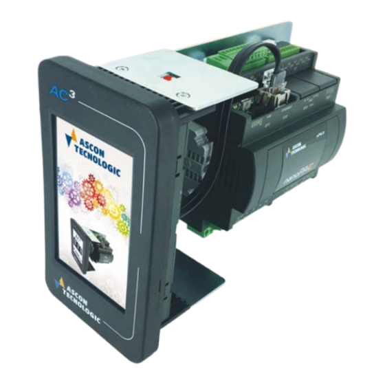
AC³nP System
Installation Manual
Installation Manual
M.I. AC³nP-00/19.02
Code: ISTR-MI AC³nPENG00
Table of
Contents
Previous
Page
Next
Page
1
2
3
4
5
Advertisement
Table of Contents
Need help?
Do you have a question about the AC3nP and is the answer not in the manual?
Ask a question
Questions and answers
Related Manuals for Ascon tecnologic AC3nP
Control Systems ASCON TECNOLOGIC AC3 User Manual
Sigma 2 series (160 pages)
Control Systems Ascon tecnologic A01 Instruction Manual
(9 pages)
Control Systems ASCON TECNOLOGIC nP4 Installation Manual
(38 pages)
Control Systems Ascon tecnologic vP4 Installation Manual
Integrated system, cpu module with on-board display and i/o (4 pages)
Control Systems Ascon tecnologic KM3L Engineering Manual
Limit controller (16 pages)
This manual is also suitable for:
P04
Np4
Table of Contents
Print
Rename the bookmark
Delete bookmark?
Delete from my manuals?
Login
Sign In
OR
Sign in with Facebook
Sign in with Google
Upload manual
Upload from disk
Upload from URL


Need help?
Do you have a question about the AC3nP and is the answer not in the manual?
Questions and answers