EchoStar HUGHES JUPITER HT2000W User Manual
Hide thumbs
Also See for HUGHES JUPITER HT2000W:
- Manual (6 pages) ,
- User sheet (2 pages) ,
- Replacement manual (15 pages)

Related Manuals for EchoStar HUGHES JUPITER HT2000W


Summary of Contents for EchoStar HUGHES JUPITER HT2000W
- Page 1 HT2000W Satellite Modem User Guide 1041264-0001 Revision A February 15, 2017 11717 Exploration Lane, Germantown, MD 20876 Phone (301) 428-5500 Fax (301) 428-1868/2830...
- Page 2 Copyright © 2017 Hughes Network Systems, LLC All rights reserved. This publication and its contents are proprietary to Hughes Network Systems, LLC. No part of this publication may be reproduced in any form or by any means without the written permission of Hughes Network Systems, LLC, 11717 Exploration Lane, Germantown, Maryland 20876.
-
Page 3: Table Of Contents
Contents Contents ....................3 Understanding safety alert messages ............ 5 Messages concerning personal injury ..............5 Messages concerning property damage ..............5 Safety symbols ....................... 6 Additional symbols ................... 6 Chapter 1 Satellite modem overview ..............7 Description ......................7 Operating environment .................. - Page 4 Advanced Settings....................24 Wireless ......................25 LAN........................28 DNS ......................... 30 Firewall ......................30 NAT ......................... 33 QoS ......................... 35 Routing......................36 IPv6 ......................... 38 Chapter 4 LEDS ...................... 39 Front-panel LEDs ....................39 LAN port LEDs ...................... 40 Appendix A Specifications ..................
-
Page 5: Understanding Safety Alert Messages
Understanding safety alert messages Safety alert messages call attention to potential safety hazards and tell you how to avoid them. These messages are identified by the signal words DANGER, WARNING, CAUTION, or NOTICE, as illustrated below. To avoid possible property damage, personal injury, or in some cases possible death, read and comply with all safety alert messages. -
Page 6: Safety Symbols
Safety symbols The generic safety alert symbol calls attention to a potential personal injury hazard. It appears next to the DANGER, WARNING, and CAUTION signal words as part of the signal word label. Other symbols may appear next to DANGER, WARNING, or CAUTION to indicate a specific type of hazard (for example, fire or electric shock). -
Page 7: Satellite Modem Overview
Chapter 1 Satellite modem overview This user guide describes the features and operation of the HT2000W satellite modem, which provides Internet access by satellite. In this user guide, satellite modem and modem both refer to the HT2000W satellite modem. Description The HT2000W satellite modem connects to a satellite network to provide Internet service. -
Page 8: Operating Environment
• Do not press the reset/rescue button on the HT2000W unless a customer service representative tells you to do so. • The USB port is provided to support a future modem feature. Hughes does not recommend plugging anything into this port at this time. Hughes will inform you when this feature is available. -
Page 9: Operating Position
Operating position Operate the HT2000W modem only in an upright, vertical position, resting on its built-in base, as shown in Figure 2. Any other position could result in insufficient ventilation, overheating, and malfunction. Figure 2: Modem operating position Computer requirements The computer that connects to the satellite modem should meet the minimum requirements specified by the computer operating system manufacturer and the following networking and browser requirements. -
Page 10: Contact Information
Contact information If you need operational, warranty, or repair support, who you should contact depends on where you purchased your satellite modem. Please contact a customer care representative in accordance with your service agreement. Power supply information • Always use the power supply provided with the satellite modem. The modem's performance may suffer if the wrong power supply is used. -
Page 11: Connecting The Modem Power Cord
Connecting the modem power cord The HT2000W power cord connector uses a locking mechanism to ensure it stays snugly connected to the modem. Make sure the connector is oriented correctly when plugging it into the DC IN port; the flat side of the plug should face the modem’s side panel nearest to the port. - Page 12 When removing the power cord, brace the modem with one hand. Use your other hand to slide the power connector sleeve toward you (away from the modem) and pull the power cord from the DC IN port. See Figure Important: If the power cord does not easily disconnect from the DC IN port, do not force it.
-
Page 13: System Control Center
Chapter 2 System Control Center The System Control Center is a set of screens and links you can use to monitor your service and troubleshoot the satellite modem in the event of a problem. The System Control Center provides access to system status, configuration information, and online documentation. -
Page 14: Indicator Links
Figure 6: System Control Center Indicator links At the top of each System Control Center page are two indicators followed by a text link (Figure 7), as well as a language selection drop-down. Figure 7: Indicators and links Each text link navigates to a page in the System Control Center. Table 1 describes the destination page for each link. -
Page 15: Parameters Bar
• Red: The system has a problem. • Yellow: The system is operational, but under a degraded condition. • Green: The system is functioning within normal parameters. Parameters bar The parameters bar appears at the top of all System Control Center screens as shown in Figure 8. -
Page 16: System Status Page
WiFi Settings Allows the user to customize certain aspects of the modem’s Wi-Fi functionality. Note: Some of these links may not appear because they are not enabled by the service provider. System Status page The System Status page lists parameter information vital to the proper operation of the HT2000W. -
Page 17: System Information Page
System Information page The System Information page (shown in Figure 11) provides system information for the satellite modem, such as identification information, software versions, and satellite information. Figure 11: System Information page Connectivity test To test your connectivity: 1. Click the Connectivity Test link on the side panel. The Terminal/Gateway Connectivity Test panel appears in the center of the screen. -
Page 18: Built-In Self Test
4. When the test completes, the results appear in the center panel. Figure 13 shows the results of the test. Figure 13: Connectivity test results Built-in self test Use the Built-In Self Test link on the side panel to check the connectivity of the satellite modem. -
Page 19: Chapter 3 Wi-Fi Configuration
Chapter 3 Wi-Fi Configuration Getting Connected for the First Time Connecting via Ethernet 1. Using the provided Ethernet cable, connect one end of the cable to one of the open LAN ports on the rear of the HT2000W, connect the other end to your PC’s Ethernet port. -
Page 20: Basic Setup
Basic Setup Logging into your HT2000W’s Wi-Fi configuration page 1. Connect to your HT2000W. 2. Open your internet browser and navigate to http://192.168.42.1 3. You will be presented with a login screen, the default password is “admin.” 4. Click Login. Figure 15: Wi-Fi login page Changing the administrator password We recommend you change this immediately upon installation. -
Page 21: Changing Your Wi-Fi Networks' Names And Security Settings
Figure 16: Administration main page 3. New options will appear in the left panel, select Password Settings. Figure 17: Password Settings page 4. Type in your old password, followed by your new password, typed twice for verification. 5. Click Save Settings. 6. -
Page 22: Enabling Guest Networks
Figure 18: Wi-Fi Configuration main page 2. The default screen will be Wi-Fi settings. The settings listed for both 2.4GHz and 5GHz networks are as follows: SSID Enable – Enable/Disable this SSID. Default is on. Network Name (SSID) – Choose the name of your network. Default value is the same as displayed on the rear label. -
Page 23: Rebooting Your Ht2000W
Figure 19: Wi-Fi guest network configuration page 3. Guest network configuration options are as follows: SSID Enable – This box must be checked in order to enable the guest network. Default is unchecked. Network Name (SSID) – Choose the name for your guest network. Default is guest, you cannot keep this name the same for both 2.4GHz and 5GHz networks. -
Page 24: Advanced Settings
Figure 20: Modem reboot page 1. Login to your HT2000W’s Wi-Fi configuration page. 2. On the left panel, select Administration. 3. Click the Reboot option on the left panel. 4. Click the Reboot button on the page. 5. Click OK on the confirmation dialog. Figure 21: Reboot confirmation page 6. -
Page 25: Wireless
Figure 22: Advanced Setup main page Wireless Main Page On the main page you can customize the following settings: Figure 23: Wireless main page 1. Wireless Mode – Choose which protocols each band will use in operation. On 2.4GHz you can select just on protocol (b/g/n) or allow automatic control. On 5GHz you can choose a only, n only, an/ mix, or a/n/ac mix. - Page 26 Channel – Choose the wireless channel you prefer to use. For best performance, it is recommended you leave this on Auto. Bandwidth – Choose your channel bandwidth. You can select either 20MHz only, 20/40, or 20/40/80 (Only on 5GHz). By default your HT2000W will choose the maximum bandwidth based on local interference.
- Page 27 Here you can manage your WPS settings. WPS, enabled by default, allows for simple push button or PIN-based setup. This page allows you to enable/disable WPS, use the PIN-based method to connect, as well as activate the push button method, as if you had pressed the WPS button the front of your HT2000W.
-
Page 28: Lan
MAC Filtering Table MAC filtering allows you to specify only certain MAC addresses that can connect to your router. This option is disabled when WPS is enabled. Figure 26: MAC Filtering Table Main Page On the main page for LAN you can change the following settings: Figure 27: LAN main page Chapter 3 ●... - Page 29 1. LAN IP – IP address of your HT2000W. If you change this, you will need to navigate to the new address to make any further settings changes. 2. IP Subnet Mask – Subnet mask used on all devices. 3. Lease Time – How long DHCP leases are maintained for devices connected to your HT2000W.
-
Page 30: Dns
Main Page This page allows you to change your DNS server that any DHCP clients will utilize. By default, you will obtain this from your ISP. Figure 29: DNS main page Firewall Main Page This page allows you to quickly enable/disable all firewall features. Figure 30: Firewall main page Chapter 3 ●... - Page 31 Parental Controls Here you can set rules for certain client devices. Clicking Add Rule will allow you to create a new rule for one or a range of IP addresses. Figure 31: Parental Controls URL Blocking This page allows you to list specific URLs to disallow. These will be valid for all users. Figure 32: URL Blocking Chapter 3 ●...
- Page 32 Intrusion Detection This page allows you to enable/disable SPI and Anti-DoS filtering as well as discarding all pings coming from your WAN interface. Figure 33: Intrusion Detection This page allows you to add one device to the demilitarized zone, or DMZ for short. A device in the DMZ will not abide by firewall rules.
-
Page 33: Nat
IPv6 This page allows you to make port forwarding rules for IPv6. Figure 35: IPv6 Main Page This page allows to you enable/disable NAT functions. Figure 36: NAT main page Chapter 3 ● Wi-Fi Configuration 1041264-0001 Revision A... - Page 34 Port Mapping This page allows you to make custom NAT port forwarding rules. Figure 37: Port Mapping Port Triggering This page allows you setup port triggering options, specifying ports on WAN that will only be active when a specific range of ports on LAN is active. Figure 38: Port Triggering Chapter 3 ●...
-
Page 35: Qos
Main Page This page allows you to enable/disable QoS as well as bias each priority level of traffic. Figure 39: QoS main page Chapter 3 ● Wi-Fi Configuration 1041264-0001 Revision A... -
Page 36: Routing
Traffic Mapping This page allows you to setup QoS rules. Rules can made to follow either specific devices, external or internal IP addresses, as well as ports. Figure 40: Traffic Mapping Routing Main Page This page shows you the current routing table. Figure 41: Routing main page Chapter 3 ●... - Page 37 Static Route This page allows you to design a static network route. Click edit to configure a route. Figure 42: Static Route Chapter 3 ● Wi-Fi Configuration 1041264-0001 Revision A...
-
Page 38: Ipv6
IPv6 Main Page This page allows you to enable/disable IPv6 as well as provide the IPv6 prefix to use. Figure 43: IPv6 main page Chapter 3 ● Wi-Fi Configuration 1041264-0001 Revision A... -
Page 39: Chapter 4 Leds
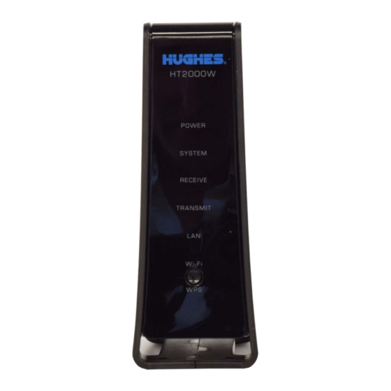
Chapter 4 LEDS Front-panel LEDs The satellite modem has six LEDs on the front panel, as shown in Figure 23. By their appearance (on, off, or blinking) the LEDs indicate the modem's operating status. The front-panel LEDs are white when lit. Figure 44: Front-panel LEDS Table 2 on page 40 explains what the modem status is when the LEDs are on, off, or... -
Page 40: Lan Port Leds
Table 2: Router status LEDs LEDS Appearance Status Power is on and the modem is functioning Red color** normally **Indicates alarm condition. Power Blinking Operating with fallback.bin (backup) version of software Off* No power Connection established with the NOC System Condition preventing full operation OK - Receive path is operational Receive... - Page 41 Figure 45: LAN port LEDS Chapter 4 ● LEDS 1041264-0001 Revision A...
-
Page 43: Appendix A Specifications
Appendix A Specifications HT2000W modem specifications The specifications for the HT2000W modem are listed in Table Table 3: HT2000W modem specifications Item Specifications Weight 1.071lb (0.486 kg) Height 7.28 inches (184.92 mm) Width 2.766 inches (70.26 mm) Depth 5.822 inches (147.88 mm) Operating temperature range 41 °F to 104 °F (5 °C to 40 °C) Above 5,000 ft (1,524 m) altitude, the maximum... -
Page 45: Appendix B Standards Compliance
Appendix B Standards compliance The HT2000W satellite modem has been certified to comply with the standards listed in Table 4. Additional information follows the table. Table 4: HT2000W standards compliance Category Standard UL60950-1 for the USA CAN/CSA-C22.2 No. 60950-1 for Canada Safety IEC60950-1 for International (CB Scheme Certification) -
Page 46: Fcc Part 15
FCC Part 15 This section applies to the HT2000W satellite modem. Standards to which conformity is declared: FCC Part 15 FCC Caution: Any changes or modifications not expressly approved by the party responsible for compliance could void the user’s authority to operate this equipment. -
Page 47: Canada Class B Warning
to which the receiver is connected. • Consult the dealer or an experienced radio TV technician for help. Canada Class B warning This Class B digital apparatus complies with Canadian ICES-003. Cet appareil numérique de la classe B est conforme à la norme NMB-003 du Canada. Class II Radio Equipment (per R&TTE Directive 1999/5/EC) Restrictions for European Union Use of this product within the frequency band 29.25 GHz to 29.5 GHz requires... - Page 48 Hereby, Hughes declares that this Class II Radio Equipment is in compliance with the essential requirements and other English relevant provisions of Directive 1999/5/EC. Hughes, vakuuttaa täten että Luokka II radiolaitteet tyyppinen Finnish laite on direktiivin 1999/5/EY oleellisten vaatimusten ja sitä koskevien direktiivin muiden ehtojen mukainen.
- Page 49 Hiermit erklärt Hughes die Übereinstimmung des Gerätes Klasse II Funkanlagen mit den grundlegenden Anforderungen und den anderen relevanten Festlegungen der Richtlinie 1999/5/EG. (Wien) ΜΕ ΤΗΝ ΠΑΡΟΥΣΑ Hughes ΔΗΛΩΝΕΙ ΟΤΙ Class II Radio Equipment] ΣΥΜΜΟΡΦΩΝΕΤΑΙ ΠΡΟΣ ΤΙΣ ΟΥΣΙΩΔΕΙΣ Greek ΑΠΑΙΤΗΣΕΙΣ ΚΑΙ ΤΙΣ ΛΟΙΠΕΣ ΣΧΕΤΙΚΕΣ ΔΙΑΤΑΞΕΙΣ ΤΗΣ ΟΔΗΓΙΑΣ 1999/5/ΕΚ...
-
Page 51: Acronyms And Abbreviations
Acronyms and abbreviations BIST – Built-in self test LAN – Local area network LED – Light emitting diode CSR – Customer service representative NetBEUI – Extended User Interface (network transfer protocol) Networking requirements NIC – Network interface controller DHCP – Dynamic Host Configuration Protocol NOC –... -
Page 53: Index
Index Modem power supply 10 connecting power cord to modem 11 disconnecting power cord from modem 11 Computer requirements 9 Modem specifications 43 Internet browser 9 networking 9 Standards compliance 45 Support 10 LAN port LEDs 40 System Control Center 13 LEDs 39 accessing 13 built-in self test 18...
Need help?
Do you have a question about the HUGHES JUPITER HT2000W and is the answer not in the manual?
Questions and answers