uAvionix microLink User And Installation Manual
Hide thumbs
Also See for microLink:
- User and installation manual (50 pages) ,
- Quick start manual (6 pages) ,
- User and installation manual (38 pages)
Table of Contents
Advertisement
Quick Links
Advertisement
Table of Contents

Related Manuals for uAvionix microLink


Summary of Contents for uAvionix microLink
- Page 1 User and Installation Guide UAV-1003064-001 Rev N Page 1 | 40...
- Page 2 retained.
-
Page 3: Revision History
08/12/2019 Updated the FCC and IC statements per the 08/28/2019 Updated the RF exposure limits per the TCB 12/18/2019 Added Updating instructions for skyStation and microLink radios 7/21/2020 Updated configuration item descriptions. Updated firmware upgrade instructions. -
Page 4: Limited Warranty
For the duration of the warranty period, uAvionix, at its sole option, will repair or replace any product which fails under normal use. Such repairs or replacement will be made at no charge to the customer for parts or labor, provided that the customer shall be responsible for any transportation cost. -
Page 5: Table Of Contents
3 Contents Revision History Limited Warranty Contents Introduction Specification microLink Radio Technology Regulatory Statements 5.2.1 FCC Statement 5.2.2 Industry Canada Statement Ground Radio System (GRS) – skyStation Airborne Radio System (ARS) Typical System Configuration Mechanical Specifications Configuration MicroLink 6.1.1 Wiring 6.1.2... - Page 6 6.5.3 Configuration Tab skyStation Configuration and Health Webpage 6.6.1 Firmware Information 6.6.2 Configuration Items 6.6.3 Status 6.6.4 Network Configuration 6.6.5 skyStation Update 6.6.6 microLink Update UAV-1003064-001 Rev N Page 6 | 40...
-
Page 7: Introduction
4 Introduction microLink is an aviation grade, miniature, Beyond Visual Line Of Sight (BVLOS) data link radio specifically designed for long range, robust, Unmanned Aircraft Systems (UAS) telemetry data links. Ideal for size, weight, power and performance sensitive applications, microLink operates in the 902-928MHz license-free ISM band. -
Page 8: Specification
5 Specification 5.1 microLink Radio Technology ● Dual radio architecture for true diversity o Path (spatial) diversity o Frequency diversity o Polarization gain ● Dynamic Medium and Multiple access, time and position synchronized, to support 100s of simultaneous links o Adaptive time and frequency spreading ●... -
Page 9: Regulatory Statements
5.2 Regulatory Statements 5.2.1 FCC Statement FCC ID: 2AFFTC2XISM This device meets the FCC requirements for RF exposure in public or uncontrolled environments. Changes or modifications not expressly approved by the party responsible for compliance could void the user’s authority to operate the equipment This device complies with part 15 of the FCC Rules. -
Page 10: Ground Radio System (Grs) - Skystation
Control Protocol Timing/Position Position Internal Environmental DO-160G Temperature Cat B2 ● All-Weather Network-Ready microLink GRS ● TCP and UDP Power Over Ethernet (POE) connectivity. ● IP67 grade enclosure. ● Dual Dipole Antennas ● Pole Mounting Kit UAV-1003064-001 Rev N Page... -
Page 11: Airborne Radio System (Ars)
5.4 Airborne Radio System (ARS) ● Transparent serial user data interface ● Plug and play with Ardupilot PixHawk autopilot ● Dual MMCX antenna connectors ● Supports NMEA/UBX GPS Sensors such as HERE2 and microFYX USER Interface (top connector) Timing/Position, CTRL Interface (bottom connector) Physica Port... -
Page 12: Typical System Configuration
5.5 Typical System Configuration Ordering Part Numbers skyStation 2 UAV-1005539-001 microLink UAV-1002868-001 GPS Options microFYX kit UAV-1002500-001 HERE2 kit UAV-1002956-001 Replacement Parts MMCX 100mm UAV-1003063-001 MMCX 200mm UAV-1003063-002 GH 6p Cable UAV-1003061001 GH 8p Cable UAV-1003062-001 UAV-1003064-001 Rev N Page... -
Page 13: Mechanical Specifications
5.6 Mechanical Specifications Airborne Radio System (ARS) UAV-1003064-001 Rev N Page 13 | 40... - Page 14 Ground Radio System (GRS) – skyStation UAV-1003064-001 Rev N Page 14 | 40...
-
Page 15: Configuration
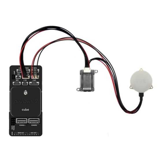
6 Configuration 6.1 MicroLink Connect the microLink ARS to an available telemetry point on the Pixhawk Autopilot. The microFYX provides GPS and PPS to both the microLink and the Pixhawk through the GPS 2 port (serial 4). 6.1.1 Wiring PIXHAWK TELEM... -
Page 16: Mission Planner Configuration
6.1.2 Mission Planner Configuration The following parameters need to be configured in Mission Planner when using microLink. The serial port depends on which telemetry port the microLink is connected to. For this instance, microLink is connected to Telem1 Function Parameter... - Page 17 The following parameters need to be configured in Mission Planner when using the microFYX and Here2 GPS in a dual GPS configuration. microFYX is on GPS 2 (serial 4) and the Here2 GPS is on GPS 1 (serial 3). Function Parameter Value Description...
-
Page 18: Skystation
6.2 skyStation Connect skyStation to a POE switch or POE power injector. UAV-1003064-001 Rev N Page 18 | 40... -
Page 19: Connection To The Poe Network
6.3 Connection to the POE Network The skyStation connects to a network via POE using an M12 X-Coded connector. POE Specifications: Parameter Value Standard 803.3af (802.3at Type1) Maximum power 15.4W 37 – 57V Voltage Range Maximum Current 350mA 20Ω Maximum Cable Resistance Supported Cabling Shielded Cat 3 and Shielded Cat 5 Supported Modes... -
Page 20: Skystation Start-Up And Connection
6.4 skyStation Start-up and Connection Connect the skyStation to a POE capable network switch. At power-up an IP address will be assigned to the skyStation by the local DHCP server. By default, the skyStation will accept TCP connections for User channel information on TCP port 42430 and the Control channel information on port 42431. -
Page 21: Configure Hop Table
At first power up the user may need to configure the Hop Table to link with the microLink. On the label on the back of the microLink is a Rradio ID. A. Enter the Radio ID into the “Radio ID Input” field on the SkyLinkApp. -
Page 22: Verify Link
6.4.3 Verify Link To verify link go to the Status Tab of the skyLinkApp. When the data arrives, skyLinkApp will begin graphing the radio link statistics. 6.4.4 Connecting to Mission Planner Download and install Mission Planner from: http://firmware.ardupilot.org/Tools/MissionPlanner/ http://ardupilot.org/planner/docs/mission-planner-installation.html Verify that the flight controller and skyStation are powered and running and that skyLinkApp.exe is receiving data. - Page 23 Select TCP as the communication mode and hit the Connect button on the upper right-hand corner. Enter the skyStation IP address as found earlier in skyLinkApp.exe and click OK. UAV-1003064-001 Rev N Page 23 | 40...
- Page 24 Enter port 42430 which is the skyStation default TCP port for Mission Planner and click OK. The TCP connection will now take off and you will see the system retrieving parameters as follows for the flight controller. The skyStation is now in place and ready to host missions. UAV-1003064-001 Rev N Page...
-
Page 25: Skylinkapp
6.5 skyLinkApp skyLinkApp.exe is the uAvionix Control channel monitoring application used for showing Status, Maps, and Configuration information. It can be connected to the skyStation in TCP mode and the ports are configurable for network flexibility. The port selection must match the skyStation Configuration page setup and the IP address is always the IP address of the skyStation. -
Page 26: Status Tab
6.5.1 Status Tab The status data is shown for both the local and the remote radios. It contains both transmit and receive information for the local and remote radios. This information includes memory queue depth information, transmit and receive data rates, frame rates, dropped frames and data totals. - Page 27 Radio throughput and statistics detail shown below. RSSI detail shown below. UAV-1003064-001 Rev N Page 27 | 40...
-
Page 28: Maps Tab
6.5.2 Maps Tab skyLinkApp.exe has a mapping tab for mapping the local radio skyStation radio as well as the remote aircraft radio. It includes latitude, longitude, altitude, GPS fix type, Slant Range and SV count. UAV-1003064-001 Rev N Page 28 | 40... -
Page 29: Configuration Tab
6.5.3 Configuration Tab skyLinkApp.exe also contains a Configuration page. This page is used for device settings and setup as well as selecting the hop table scheme for the system. UAV-1003064-001 Rev N Page 29 | 40... - Page 30 Generates the Hop Table per the Radio ID input Radio ID input allows the user to enter the airborne radio ID to match Hop Tables. Saves the Hop Table currently displayed in the Hop Table window to the device. UAV-1003064-001 Rev N Page 30 | 40...
- Page 31 The File window allows the user to save or load all the Configuration parameters to a PC. The Versions window shows the microLink radio information for both the Local radio, and the Remote radio when a Link has been made.
-
Page 32: Skystation Configuration And Health Webpage
6.6 skyStation Configuration and Health Webpage The skyStation IP address can be determined by accessing the local DHCP server and reviewing the connected devices or by using industry accepted network scanning tools. Directions for each DHCP server, router, or network scanning tool differ. Refer to the instruction manual for these devices or tools to help determine the IP address assigned to the skyStation. - Page 33 UAV-1003064-001 Rev N Page 33 | 40...
-
Page 34: Firmware Information
The skyStation firmware version, microLink radio version and the microLink radio ID associated are displayed here. The user can update the skyStation through the webpage by clicking the “update” link and the microLink Radio through the SkyLinkApp. see section 6.6.5 and 6.6.6. -
Page 35: Status
6.6.3 Status The Status Information section shows real time statistics updated once every second. It will show skyStation Up Time, GPS and PPS metrics. It will also show SkyLine metrics when connected through to the websocket. UAV-1003064-001 Rev N Page 35 | 40... -
Page 36: Network Configuration
6.6.4 Network Configuration Clicking the Network Configuration link on the main landing page will forward you to the Network Configuration page where the user can adjust the network connectivity settings used by the skyStation when a DHCP server is not available. Configuration Item Description IP Address... -
Page 37: Skystation Update
6.6.5 skyStation Update The firmware on the skyStation can be updated through the skyStation Configuration Webpage by clicking the Update link next to the version number. Choose the appropriate file to upload and click Start Update. DO NOT power off the skyStation or close the web browser until the update is complete. - Page 38 When the file transfer is complete, click the Main Page link to return to the skyStation Configuration Webpage*. The version number on the Configuration Webpage should reflect the firmware version uploaded. * The reboot of the skystation could take up to 45s to complete UAV-1003064-001 Rev N Page...
-
Page 39: Microlink Update
6.6.6 microLink Update The microLink Radio on the skyStation can be updated using the SkyLinkApp. First connect the SkyLinkApp to the skyStation following the steps in section 6.4. In the upper right hand corner click the “Radio FW Update” button. - Page 40 Click “Flash” DO NOT power off or disconnect the device until the flash is complete. UAV-1003064-001 Rev N Page 40 | 40...
Need help?
Do you have a question about the microLink and is the answer not in the manual?
Questions and answers