
Related Manuals for uAvionix George G2i


Summary of Contents for uAvionix George G2i
- Page 1 _________________________________________________________________ George G2i User Guide UAV-1005573-001 Rev D Page 1 of 46...
- Page 2 retained.
-
Page 3: Revision History
_________________________________________________________________ 1 Revision History Revision Date Comments 6/9/2021 Initial release 8/29/2021 G2 updates 9/5/2021 SS2 and Compass Updates 10/19/2021 Update parameters UAV-1005573-001 Rev D Page 3 of 46... -
Page 4: Limited Warranty
For the duration of the warranty period, uAvionix, at its sole option, will repair or replace any product which fails under normal use. Such repairs or replacement will be made at no charge to the customer for parts or labor, provided that the customer shall be responsible for any transportation cost. -
Page 5: Table Of Contents
_________________________________________________________________ 3 Contents Revision History Limited Warranty Contents Specification George Autopilot Technology Regulatory Statements 4.2.1 FCC Statement 4.2.2 Industry Canada Statement Mechanical Specifications Installation George Mechanical Installation George Electrical Installation 5.2.1 Example Electrical Connection for eVTOL 5.2.2 George RF Connections skyStation Mechanical Installation 5.3.1 Tripod Installation... - Page 6 _________________________________________________________________ 6.3.3 Compass Configuration 6.3.4 Remote Connection to George skyLinkApp.exe 6.4.1 Status Tab 6.4.2 Maps Tab 6.4.3 Configuration Tab Configuration and Health Webpage 6.5.1 Firmware Information 6.5.2 Configuration Items 6.5.3 Network Configuration 6.5.4 skyStation Update 6.5.5 microLink Update UAV-1005573-001 Rev D Page 6 of 46...
-
Page 7: Specification
Input Voltage/Power 2S-12S 2.5W Size 44x40x63mm Weight 63 grams Operating Temp -10° to 55° C Internal Peripherals Core cubeOrange uAvionix microLink ADS-B uAvionix pingRXpro Compass 3 axis RM3100 Airspeed SDP33 External Interfaces Servo/ESC Outputs RS232 Serial IO UAVCAN IO ADC Inputs... -
Page 8: Regulatory Statements
_________________________________________________________________ 4.2 Regulatory Statements 4.2.1 FCC Statement FCC ID: 2AFFTC2XISM This device meets the FCC requirements for RF exposure in public or uncontrolled environments. Changes or modifications not expressly approved by the party responsible for compliance could void the user’s authority to operate the equipment This device complies with part 15 of the FCC Rules. -
Page 9: Mechanical Specifications
_________________________________________________________________ 2) l’appareil doit accepter tout brouillage radioélectrique subi, même si le brouillage est susceptible d’en compromettre le fonctionnement.” 4.3 Mechanical Specifications UAV-1005573-001 Rev D Page 9 of 46... -
Page 10: Installation
_________________________________________________________________ 5 Installation 5.1 George Mechanical Installation Mount the George AutoPilot on a flat solid surface near the Center of Gravity (CG) of the aircraft. Mount the George AutoPilot so that the arrow on top of the AutoPilot is pointed towards the nose of the aircraft. Use three M3 or #5 size screws to secure the George AutoPilot to the airframe at the three mounting locations. -
Page 11: George Electrical Installation
_________________________________________________________________ 5.2 George Electrical Installation Integrate the George AutoPilot to your platform. George offers 9 PWM channels, 2 external serial connections and a power module capable of supporting up to two 6s LiPo batteries. UAV-1005573-001 Rev D Page 11 of 46... -
Page 12: Example Electrical Connection For Evtol
_________________________________________________________________ 5.2.1 Example Electrical Connection for eVTOL eVTOL Resource Description Parameter Value Parameters PWM_CH1 Starboard Elevon Servo FUNCTION 80:VTailRight PWM_CH2 Port Aileron Servo FUNCTION 4:Aileron PWM_CH3 Pusher Motor FUNCTION 70:Throttle PWM_CH4 Starboard Aileron Servo FUNCTION 4:Aileron PWM_CH5 Starboard Forward Motor 1 FUNCTION 33:Motor1 PWM_CH6 Port Forward Motor 3 FUNCTION... - Page 13 _________________________________________________________________ microLink ADS-B antennas antenna truFYX Power Adapter SERIAL_RX4 UAV-1005573-001 Rev D Page 13 of 46...
-
Page 14: George Rf Connections
_________________________________________________________________ 5.2.2 George RF Connections Three antennas are included with the George Autopilot, two 915 MHz dipole antennas for the C2 radio, and one feeder ADS-B antenna. The 915 MHz Dipole antennas should be mounted in a vertical orientation. C2 Antenna ADS-B Antenna UAV-1005573-001 Rev D Page 14 of 46... -
Page 15: Skystation Mechanical Installation
_________________________________________________________________ 5.3 skyStation Mechanical Installation 5.3.1 Tripod Installation Mount the skyStation to a conventional tripod using a standard ¼”-20 screw. Mounting location is on the bottom of the skyStation as shown below. Place the skyStation at a vantage point to achieve adequate coverage and optimal line-of-sight to the autopilot. -
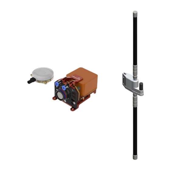
Page 16: Pole Installation
_________________________________________________________________ 5.3.2 Pole Installation Attach the pole mounting bracket to the skyStation and secure using the two supplied M5 shoulder screws. Use the supplied hose clamps to secure the skyStation to the mounting pole. Antenna orientation should be vertical. UAV-1005573-001 Rev D Page 16 of 46... -
Page 17: Skystation Electrical
_________________________________________________________________ 5.4 skyStation Electrical The skyStation connects to a network via POE using an M12 connector. Suggested cable part #: 142M2X15050 Suggested accessory: RJ45 Coupler POE Specifications: Parameter Value Standard 803.3af (802.3at Type1) Maximum power 15.4W 37 – 57V Voltage Range Maximum Current 350mA Maximum Cable Resistance... - Page 18 _________________________________________________________________ POE Switch UAV-1005573-001 Rev D Page 18 of 46...
-
Page 19: Configuration
_________________________________________________________________ 6 Configuration 6.1 George Start-up and Connection Power on the George AutoPilot by connecting to the aircraft power system. Once George acquires a GPS lock, a C2 link can be made. A C2 link can only be made when a skyStation is powered on within proximity. -
Page 20: Skystation Start-Up And Connection
_________________________________________________________________ 6.2 skyStation Start-up and Connection Connect the skyStation to a POE capable network switch. At power-up an IP address will be assigned to the skyStation by the local DHCP server. By default, the skyStation will accept TCP connections for User channel information on TCP port 42430 and the Control channel information on port 42431. -
Page 21: Configure Hop Table
_________________________________________________________________ 6.2.2 Configure Hop Table Once connected via the SkyLinkApp, go to the Configuration tab. At first power up the user may need to configure the Hop Table to link with the George G2. On the label on the George G2 is a radio ID. A. -
Page 22: Verify Link
_________________________________________________________________ 6.2.3 Verify Link To verify link go to the Status Tab of the skyLinkApp. When the data arrives, skyLinkApp will begin graphing the radio link statistics. UAV-1005573-001 Rev D Page 22 of 46... -
Page 23: Connecting George To Mission Planner
_________________________________________________________________ 6.3 Connecting George to Mission Planner Download and install Mission Planner from: http://firmware.ardupilot.org/Tools/MissionPlanner/ http://ardupilot.org/planner/docs/mission-planner-installation.html 6.3.1 George Direct Connect Connect the George AutoPilot directly to a PC using a micro-USB cable. The connection point on the George AutoPilot is on the side of the Cube Orange. - Page 24 _________________________________________________________________ Note: On first power up, it may be required to setup the AutoPilot with Mission Planner. To do this, keep Mission Planner disconnected from the George AutoPilot. Go to the SETUP tab and the Install Firmware section. George AutoPilot comes default with an Airplane 4.1.2 configuration. Select your platform style and follow the instructions on Mission Planner to setup the AutoPilot.
-
Page 25: George Parameters
MavLink 1 Protocol **ADS-B SERIAL5_BAUD Baud Rate = 57600 SERIAL5_PROTOCOL MavLink 1 Protocol SERIAL5_OPTIONS 1024 Don’t forward mavlink to/from ***ADSB_TYPE Enable uAvionix ADSB ADSB_EMIT_TYPE Emitter Category = UAV ADSB_RF_CAPABLE RX UAT and 1090ES ADSB_RF_SELECT RX Only Battery BATT_MONITOR Analog Voltage and Current BATT_AMP_PERVLT 27.7347... - Page 26 _________________________________________________________________ ***In Plane and Copter versions predating 4.1.0, ADSB_Type is replaced with ADSB_Enable. Click “Write Params” when finished and cycle the power. UAV-1005573-001 Rev D Page 26 of 46...
-
Page 27: Compass Configuration
_________________________________________________________________ 6.3.3 Compass Configuration George contains an internal RM3100 compass for heading reference. The RM3100 delivers improved accuracy over the Cube integrated compass and is connected via the internal i2C bus. George will automatically detect the RM3100 and assign a DevID, no parameter changes are necessary for the RM3100 to be properly identified. -
Page 28: Remote Connection To George
_________________________________________________________________ 6.3.4 Remote Connection to George The George AutoPilot must be preconfigured to establish a remote connection. Follow procedures in sections 6.3.1 and 6.3.2 to configure the AutoPilot. Verify that the George AutoPilot and skyStation are powered, linked, and that skyLinkApp.exe is receiving data. Run Mission Planner and select the communications drop down menu. - Page 29 _________________________________________________________________ Enter the User TCP port number as shown on the skyStation configuration page (see section 6.4.3) and click OK. The default port number is 42430. Mission Planner will begin retrieving parameters when a successful TCP connection has been made. UAV-1005573-001 Rev D Page 29 of 46...
- Page 30 _________________________________________________________________ The user now has full remote access to the George AutoPilot. UAV-1005573-001 Rev D Page 30 of 46...
-
Page 31: Skylinkapp.exe
_________________________________________________________________ 6.4 skyLinkApp.exe skyLinkApp.exe is the uAvionix Control channel monitoring application used for showing Status, Maps, and Configuration information. It can be connected to the skyStation in TCP mode and the ports are configurable for network flexibility. The mode and port selection must match the skyStation Configuration page setup and the IP address is always the IP address of the skyStation. -
Page 32: Status Tab
_________________________________________________________________ 6.4.1 Status Tab The status data is shown for both the local and the remote radios. It contains both transmit and receive information for the local and remote radios. This information includes memory queue depth information, transmit and receive data rates, frame rates, dropped frames and data totals. - Page 33 _________________________________________________________________ Radio throughput and statistics detail shown below. RSSI detail shown below. UAV-1005573-001 Rev D Page 33 of 46...
-
Page 34: Maps Tab
_________________________________________________________________ 6.4.2 Maps Tab skyLinkApp.exe has a mapping tab for mapping the local radio skyStation radio as well as the remote aircraft radio. It includes latitude, longitude, altitude, GPS fix type, Slant Range and SV count. UAV-1005573-001 Rev D Page 34 of 46... -
Page 35: Configuration Tab
_________________________________________________________________ 6.4.3 Configuration Tab skyLinkApp.exe also contains a Configuration page. This page is used for device settings and setup as well as selecting the hop table scheme for the system. UAV-1005573-001 Rev D Page 35 of 46... - Page 36 _________________________________________________________________ Generates the Hop Table per the DeviceID input DeviceID input allows the user to enter the airborne radio ID to match Hop Tables. Saves the Hop Table currently displayed in the Hop Table window to the device. UAV-1005573-001 Rev D Page 36 of 46...
- Page 37 _________________________________________________________________ Shows current device configuration. Clicking the button will pull the configuration parameters currently stored on the device and display them in the window. Clicking the button will push any new configuration parameters to the device. The File window allows the user to save or load all the Configuration parameters to a PC.
-
Page 38: Configuration And Health Webpage
_________________________________________________________________ 6.5 Configuration and Health Webpage The skyStation IP address can be determined by accessing the local DHCP server and reviewing the connected devices or by using industry accepted network scanning tools. Directions for each DHCP server, router, or network scanning tool differ. Refer to the instruction manual for these devices or tools to help determine the IP address assigned to the skyStation. - Page 39 _________________________________________________________________ UAV-1005573-001 Rev D Page 39 of 46...
-
Page 40: Firmware Information
_________________________________________________________________ 6.5.1 Firmware Information The skyStation firmware version, microLink radio version and the microLink radio ID associated are displayed here. The user can update the skyStation through the webpage by clicking the “update” link and the microLink Radio through the SkyLinkApp. see section 0 and 0. 6.5.2 Configuration Items Configuration Item Description... -
Page 41: Network Configuration
_________________________________________________________________ The Status Information section shows real time statistics updated once every second. It will show skyStation Up Time, GPS and PPS metrics. It will also show SkyLine metrics when connected through to the websocket. 6.5.3 Network Configuration Clicking the Network Configuration link on the main landing page will forward you to the Network Configuration page where the user can adjust the network connectivity settings used by the skyStation when a DHCP server is not available. - Page 42 _________________________________________________________________ Configuration Item Description IP Address This is the IP address number of the skyStation which will be used when a DHCP server is not available. The network administrator should assign this number. Subnet Mask Mask used with the skyStation IP address to differentiate between local and remote subnet destinations.
-
Page 43: Skystation Update
_________________________________________________________________ 6.5.4 skyStation Update The firmware on the skyStation can be updated through the skyStation Configuration Webpage by clicking the Update link next to the version number. Choose the appropriate file to upload and click Start Update. DO NOT power off the skyStation or close the web browser until the update is complete. - Page 44 _________________________________________________________________ When the file transfer is complete, click the Main Page link to return to the skyStation Configuration Webpage. The version number on the Configuration Webpage should reflect the firmware version uploaded. UAV-1005573-001 Rev D Page 44 of 46...
-
Page 45: Microlink Update
_________________________________________________________________ 6.5.5 microLink Update The microLink Radio on the skyStation can be updated using the SkyLinkApp. First connect the SkyLinkApp to the skyStation following the steps in section 6.2. In the upper right hand corner click the “Radio FW Update” button. A new window will open. - Page 46 _________________________________________________________________ Click “Flash” DO NOT power off or disconnect the device until the flash is complete. UAV-1005573-001 Rev D Page 46 of 46...
Need help?
Do you have a question about the George G2i and is the answer not in the manual?
Questions and answers