uAvionix microLink User And Installation Manual
Hide thumbs
Also See for microLink:
- User and installation manual (50 pages) ,
- Quick start manual (6 pages) ,
- Quick start manual (6 pages)
Table of Contents
Advertisement
Quick Links
Advertisement
Table of Contents

Related Manuals for uAvionix microLink


Summary of Contents for uAvionix microLink
- Page 1 User and Installation Guide UAV-1003064-001 Rev J Page 1 | 38...
- Page 2 retained.
-
Page 3: Revision History
08/12/2019 Updated the FCC and IC statements per the 08/28/2019 Updated the RF exposure limits per the TCB 12/18/2019 Added Updating instructions for skyStation and microLink radios 7/21/2020 Updated configuration item descriptions. Updated firmware upgrade instructions. -
Page 4: Limited Warranty
For the duration of the warranty period, uAvionix, at its sole option, will repair or replace any product which fails under normal use. Such repairs or replacement will be made at no charge to the customer for parts or labor, provided that the customer shall be responsible for any transportation cost. -
Page 5: Table Of Contents
3 Contents Revision History ................... 3 Limited Warranty .................. 4 Contents ....................5 Introduction ..................7 Specification ..................8 microLink Radio Technology ............8 Regulatory Statements ..............9 5.2.1 FCC Statement................ 9 5.2.2 Industry Canada Statement ............. 9 Ground Radio System (GRS) – skyStation ......... 11 Airborne Radio System (ARS) ............ - Page 6 6.5.1 Updating skyStation .............. 34 6.5.2 Updating Airborne microLink Radio ........37 UAV-1003064-001 Rev J Page 6 | 38...
-
Page 7: Introduction
4 Introduction microLink is an aviation grade, miniature, Beyond Visual Line Of Sight (BVLOS) data link radio specifically designed for long range, robust, Unmanned Aircraft Systems (UAS) telemetry data links. Ideal for size, weight, power and performance sensitive applications, microLink operates in the 902-928MHz license-free ISM band. -
Page 8: Specification
5 Specification 5.1 microLink Radio Technology • Dual radio architecture for true diversity o Path (spatial) diversity o Frequency diversity o Polarization gain • Dynamic Medium and Multiple access, time and position synchronized, to support 100s of simultaneous links o Adaptive time and frequency spreading •... -
Page 9: Regulatory Statements
5.2 Regulatory Statements 5.2.1 FCC Statement FCC ID: 2AFFTC2XISM This device meets the FCC requirements for RF exposure in public or uncontrolled environments. Changes or modifications not expressly approved by the party responsible for compliance could void the user’s authority to operate the equipment This device complies with part 15 of the FCC Rules. - Page 10 Le présent appareil est conforme aux CNR d’Industrie Canada applicables aux appareils radio exempts de licence. L’exploitation est autorisée aux deux conditions suivantes : 1) l’appareil ne doit pas produire de brouillage; 2) l’appareil doit accepter tout brouillage radioélectrique subi, même si le brouillage est susceptible d’en compromettre le fonctionnement.”...
-
Page 11: Ground Radio System (Grs) - Skystation
5.3 Ground Radio System (GRS) – skyStation • All-Weather Network-Ready microLink GRS • TCP and UDP Power Over Ethernet (POE) connectivity. • IP67 grade enclosure. • Dual Dipole Antennas • Pole Mounting Kit Specification Value Input Power 13W Peak Size... -
Page 12: Airborne Radio System (Ars)
5.4 Airborne Radio System (ARS) • Transparent serial user data interface • Plug and play with Ardupilot PixHawk autopilot • Dual MMCX antenna connectors • Supports NMEA/UBX GPS Sensors such as HERE2 and microFYX USER Interface (top connector) Timing/Position, Control Interface (bottom connector) Pin Type Physical Port... -
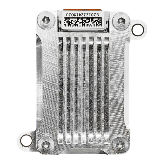
Page 13: Mechanical Specifications
Ordering Part Numbers skyStation 2 UAV-1005539-001 microLink UAV-1002868-001 GPS Options microFYX kit UAV-1002500-001 HERE2 kit UAV-1002956-001 Replacement Parts MMCX 100mm UAV-1003063-001 MMCX 200mm UAV-1003063-002 GH 6p Cable UAV-1003061001 GH 8p Cable UAV-1003062-001 5.6 Mechanical Specifications Airborne Radio System (ARS) UAV-1003064-001... - Page 14 UAV-1003064-001 Rev J Page 14 | 38...
-
Page 15: Configuration
6 Configuration 6.1 skyStation Connect skyStation to a POE switch or POE power injector. UAV-1003064-001 Rev J Page 15 | 38... -
Page 16: Connection To The Poe Network
6.2 Connection to the POE Network The skyStation connects to a network via POE using an M12 X-Coded connector. POE Specifications: Parameter Value Standard 803.3af (802.3at Type1) Maximum power 15.4W 37 – 57V Voltage Range Maximum Current 350mA 20Ω Maximum Cable Resistance Supported Cabling Shielded Cat 3 and Shielded Cat 5 Supported Modes... -
Page 17: Skystation Start-Up And Connection
6.3 skyStation Start-up and Connection To setup the microLink and skyStation quickly with default configuration, see the “microLink Quick Start Guide.pdf”. Connect the skyStation to a POE capable network switch. At power-up an IP address will be assigned to the skyStation by the local DHCP server. By default, the skyStation will start broadcasting the User channel information on TCP port 42430 and the Control channel information on port 42431. -
Page 18: Connecting To Mission Planner
6.3.2 Connecting to Mission Planner Download and install Mission Planner from: http://firmware.ardupilot.org/Tools/MissionPlanner/ http://ardupilot.org/planner/docs/mission-planner-installation.html Verify that the flight controller and skyStation are powered and running and that skyLinkApp.exe is receiving data. Run Mission Planner and select the communications drop down menu. Select TCP as the communication mode and hit the Connect button on the upper right-hand corner. - Page 19 Enter port 42430 which is the skyStation default TCP port for Mission Planner and click OK. The TCP connection will now take off and you will see the system retrieving parameters as follows for the flight controller. UAV-1003064-001 Rev J Page 19 | 38...
-
Page 20: Skylinkapp.exe
The skyStation is now in place and ready to host missions. 6.3.3 skyLinkApp.exe skyLinkApp.exe is the uAvionix Control channel monitoring application used for showing Status, Maps, and Configuration information. It can be connected to the skyStation in TCP mode and the ports are configurable for network flexibility. -
Page 21: Status Tab
There is also a KML logging feature for importation into mapping software Logging may also be captured in comma separated value (CSV) format. 6.3.4 Status Tab The status data is shown for both the local and the remote radios. It contains both transmit and receive information for the local and remote radios. - Page 22 RSSI detail shown below. UAV-1003064-001 Rev J Page 22 | 38...
-
Page 23: Maps Tab
6.3.5 Maps Tab skyLinkApp.exe has a mapping tab for mapping the local radio skyStation radio as well as the remote aircraft radio. It includes latitude, longitude, altitude, GPS fix type, Slant Range and SV count. 6.3.6 Configuration Tab skyLinkApp.exe also contains a Configuration tab. This tab is used for device settings and setup as well as system selecting the hop table scheme for the system. - Page 24 6.3.6.1 Airborne Radio System (ARS) Configuration Connect the microLink radio to your PC using the USB to serial adapter board marked CNTL. The CNTL board connects to the radio’s bottom connector. Note that a GPS signal is not required to perform configuration operations on the radio.
- Page 25 On the Configuration Tab: • Default to ISM Hopping Table • Save Hop Table to Device o Station Type: Airborne (Do not modify) o UTC Pulse Polarity: Positive (Do not modify) o User Port Baud Rate: 57600 o GPS Port Baud Rate: 115200 (Do not modify) o Control Port Baud Rate: 115200 o Check Frame When Stale o Framer MTU: 240...
- Page 26 6.3.6.2 Ground Radio System (GRS) Configuration Connect as shown below then run the skyLinkApp. UAV-1003064-001 Rev J Page 26 | 38...
- Page 27 Select Port and set UDP / TCP as configured. On the Configuration Tab: • Default to ISM Hopping Table • Save Hop Table to Device o Station Type: Ground (Do not modify) o UTC Pulse Polarity: Positive (Do not modify) o User Port Baud Rate: 57600 o GPS Port Baud Rate: 115200 (Read only) o Control Port Baud Rate: 115200 (Read only)
- Page 28 6.3.6.3 Hop Masking The radio can be configured to not transmit and/or not receive on a given hop. To enable the controls for this feature, check the “Use Masked Hop Tables” checkbox on the configuration tab. UAV-1003064-001 Rev J Page 28 | 38...
- Page 29 Two new columns, Tx Enabled and Rx Enabled will appear and 8 new buttons for mask manipulation will appear. To select which hops to enable or disable, simply check or uncheck the check box in the Hop Table. The buttons provide useful shortcuts to speed up the manipulation of all 50 hops.
- Page 30 ACTIVE/STANDBY state untouched. Note that the Hop Table masking will return to its saved configuration when returning to ACTIVE from STANDBY. 6.3.6.5 Remote Configuration Over the air or Remote Configuration is possible. This may be useful when the airborne radio is installed on an aircraft and it is difficult to remove it for configuration.
-
Page 31: Skystation Configuration And Health Webpage
6.4 skyStation Configuration and Health Webpage The skyStation IP address can be determined by accessing the local DHCP server and reviewing the connected devices or by using industry accepted network scanning tools. Directions for each DHCP server, router, or network scanning tool differ. Refer to the instruction manual for these devices or tools to help determine the IP address assigned to the skyStation. - Page 32 UAV-1003064-001 Rev J Page 32 | 38...
-
Page 33: Configuration Items
6.4.1 Configuration Items Configuration Item Description Data Mux IP Address When this parameter is 0.0.0.0, the skyStation will act as a TCP server and listen for incoming connections. Alternatively, if this address is a valid IP address, the skyStation will act as a TCP client and will attempt to connect to a TCP server listening on [User TCP IP Address : User TCP Port ]. -
Page 34: Status
6.5 Updating Devices The following sections outline the steps to update the firmware on the microLink radios and the skyStation. There are two updating procedures, one for the skyStation firmware and one for the airborne radio. You will need to download the PingBootFlasher.exe to update the airborne radio. - Page 35 When the IP address is known, open a web browser and in the URL search bar enter the IP address. Click the Update link next to the version number. Choose the appropriate file to upload and click Start Update. DO NOT power off the skyStation or close the web browser until the update is complete.
- Page 36 When the file transfer is complete, click the Main Page link to return to the skyStation Configuration Webpage. The version number on the Configuration Webpage should reflect the firmware version uploaded. UAV-1003064-001 Rev J Page 36 | 38...
- Page 37 6.5.2 Updating Airborne microLink Radio Connect the microLink airborne radio to a Mac or PC using the supplied “CNTL” USB to Serial adapter, 6 pin GH cable, and a micro-USB cable. Connect the microLink radio through the Control port (bottom connector).
- Page 38 DO NOT DISCONNECT THE MICROLINK RADIO OR CLOSE THE PING BOOT FLASHER UNTIL UPDATE IS COMPLETE When update is complete, unplug the microLink radio and plug it back into the Mac or PC. Reconnect the PingBootFlasher to the microLink radio and verify the App Version has updated.
Need help?
Do you have a question about the microLink and is the answer not in the manual?
Questions and answers