Advertisement
Quick Links
INSTALLATION AND OPERATING
INSTRUCTIONS
LUX PRODUCTS CORPORATION
Mt. Laurel, New Jersey 08054, USA
www.luxproproducts.com
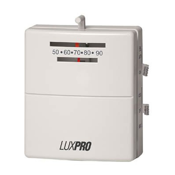
PSM40SA
HEATING & COOLING THERMOSTAT
ATTENTION : not for use with
compressors without
time delays.
SPECIFICATIONS
ELECTRICAL RATING ......24 Vac (30 Vac Maximum)
SWITCH ACTION ......................Open contact switch
ANTICIPATOR RATING
(HEATING)....................................0.15A to 1.2A
(COOLING)...................................Fixed 24 VAC
TEMPERATURE RANGE .......................50°F to 90°F
INSTALLATION & OPERATION
1). THERMOSTAT LOCATION
For accurate temperature control and comfort, correct
location is very important. On new installations, the
guidelines listed below should be followed as closely as
possible. When replacing an old thermostat, install the
new one in the same location unless these conditions
suggest otherwise.
1. Locate the thermostat on an inside wall about five
feet above the floor, where it is easy to install and
adjust. It should be in a room that is used often, such
as a family room.
2. Do not install it where there are unusual heating
conditions, such as direct sunlight, close to a lamp,
radio, television, radiator, register, near a fireplace, or
other heat producing appliance. Also, check for hot
water pipes within the wall, or a stove on the other
side of the wall.
LUXPRO
52047
LIT-12013411
© 2007 LUX PRODUCTS CORPORATION. ALL RIGHTS RESERVED
3. Do not locate in unusual cooling conditions, such as
on an outside wall, or one separating an unheated
room, or in drafts from stairwells, doors, or windows.
4. Do not locate in a damp or humid area. This can
shorten thermostat life due to corrosion.
5. Do not locate where air circulation is poor, such as in
a corner, alcove, or behind an open door.
6. Do not install until all construction work and painting
have been completed.
2) TOOLS REQUIRED
Wirestripper or knife, drill with 3 ⁄16" bit, screwdriver,
level and a pencil.
3) REMOVING OLD THERMOSTAT
Please read all instructions carefully. As you complete
each step, check the adjoining square
■ ■
Disconnect electricity and turn off gas to the heater.
■ ■
Remove cover from old thermostat.
■ ■
Disconnect wires from thermostat, making sure they
do not fall back inside the wall. Make note of wires
and to which terminals they are attached as you
disconnect them. For example: "Yellow wire to
terminal Y, Red wire to terminal RH," etc.
Strip insulation 3 ⁄8" from wire ends and clean off any
■ ■
corrosion.
■ ■
Loosen all screws on the old thermostat and remove
it from the wall.
■ ■
Fill wall opening with non-combustible insulation to
prevent drafts from affecting thermostat.
4) INSTALLING NEW THERMOSTAT
■ ■
Place new decorative wall plate (if supplied), Figure 4,
over wall opening. Decorative wall plate can
optionally be left off.
■ ■
Remove Front Cover of new thermostat by inserting a
finger in the side of the thermostat and gently prying
away each corner. Remove Base, Figure 2, from Sub-
Base, Figure 3, by loosening three captive screws.
■ ■
Place Sub-Base, Figure 3, on wallplate over wall
opening. Mark wall with pencil at mounting holes as
shown in Figure 2. Now lay wallplate and Sub-Base to
the side.
■ ■
Drill two holes with 3/16" bit, 1" deep.
■ ■
Insert plastic screw anchors into drilled holes, flush
with wall surface.
■ ■
Bring wires through large hole in decorative wall plate
and through Hole For Wires in Sub-Base.
■ ■
Referring to your notes and the following diagrams,
attach wires to terminal screws shown in Figure 2.
Make sure bare metal wires do not touch each other.
Push all excess wire back into wall.
■ ■
✓.
1
Advertisement

Subscribe to Our Youtube Channel
Related Manuals for Lux Products LUXPRO PSM40SA


Summary of Contents for Lux Products LUXPRO PSM40SA
- Page 1 Push all excess wire back into wall. other heat producing appliance. Also, check for hot water pipes within the wall, or a stove on the other side of the wall. © 2007 LUX PRODUCTS CORPORATION. ALL RIGHTS RESERVED...
- Page 2 WIRING DIAGRAMS Cooling Systems Heating Systems FAN RELAY FAN RELAY COOLING COMPRESSOR COOLING COMPRESSOR HEATING CONTROL HEATING CONTROL HEATING TRANSFORMER HEATING TRANSFORMER DAMPER OR CHANGEOVER VALVE DAMPER OR CHANGEOVER VALVE (POWERED IN HEAT) (POWERED IN HEAT) DAMPER OR CHANGEOVER VALVE DAMPER OR CHANGEOVER VALVE (POWERED IN COOL) (POWERED IN COOL)
- Page 3 These diagrams below are provided for new installations or unreferenced wires. TYPICAL HOOKUP FOR 2-WIRE TYPICAL HOOKUP FOR 3-WIRE TYPICAL COOLING AND 24V HEATING SYSTEM AND HEAT SYSTEM IF THIRD HEATING SYSTEM MILLIVOLT SYSTEM WIRE IS FAN WIRE (4-WIRE) W RH W RH W RH VALVE...
- Page 4 FIGURE 1 in materials or workmanship within three years of date FRONT COVER of original purchase, LUX Products Corporation will, at its option, repair or replace it. This warranty does not cover damage by accident, misuse, or failure to follow installation instructions. Implied warranties are limited in duration to three years from date of original purchase.
Need help?
Do you have a question about the LUXPRO PSM40SA and is the answer not in the manual?
Questions and answers