Table of Contents
Advertisement
Quick Links
Quick Installation Guide
Before operating the unit, please read this manual thoroughly and
keep it for future reference.
Please access our website and download necessary IPAdminTool first:
http://www.rivatech.de/en/downloads/software
NC3512(63)11-2015-A
About the manuals
This manual provides the instructions for the quick installation
and the basic configuration of your IP device. For more detailed
information about the installation and configuration, refer to the
device's installation guide and the web page user's manual.
Part names and functions
Please check the name and the position of each part by
referring to the following image.
Terminal connector
DO
DI DC 12V
C 1 C 1 - +
Terminal Connector: Connect the provided 6 pin terminal block for
a sensor, an alarm and a DC12V power cable.
Ethernet Connector: Connect an RJ-45 LAN cable for 10/100 Base-T
Ethernet (PoE supported).
Reset Button: Press the button either for the restart or the factory
default of the device. For restart,
seconds while the device is powered on.
reboot. For factory default,
the device is powered on.
mircoSD/SDHC Card Slot: Insert a card up to 32GB supported.
Class 4 or the above is recommended for HD recording.
Installation
There is only one type of mounting explained in this manual. Refer
to the device's installation guide for more various mounting types.
ETHERNET
WIRE
1) Place the installation template included in the package on a
desired installation surface.
2) Drill three holes for the plastic anchors based on the template
paper, and insert the plastic anchors into the holes. (In case you
need to route the cables through the mounting surface, drill the
hole to pass the cables based on the size of the cable entry hole).
Reset
button
Ethernet
connector
micro
SD/SDHC card slot
1.
press the button only for 2
2.
Wait for the system to
1.
press the button for 10 seconds while
2.
Wait for the system to reboot.
ETHERNET
WIRE
M4x30 screw
3) Attach the provided silicon waterproof band to the bottom of
the camera body for the prevention of water permeation.
4) Open the dome cover with the provided L wrench (3mm),
install the provided ferrite core to the LAN cable by referring to
the squared image on the bottom left of this page, and connect
all the necessary cables dropped from the ceiling to the
corresponding connectors on the camera.
5) Prepare the screws (M4x30) with the O-rings inserted. Then,
place the camera body to match the alignment holes with the
corresponding plastic anchors, insert the O-ring inserted screws
into the screw holes on the camera body, and tighten them into
the plastic anchors with a screw driver.
6) Adjust the angle of the camera. Refer to the section,
Adjusting angle of camera for more details.
7) Adjust zoom and focus of the camera. Refer to Adjusting
zoom and focus for more details.
8) Reattach the dome cover to the camera body by aligning the
alignment marks on both the dome cover and the camera body.
9) Once the dome cover and the camera body are properly
aligned, tighten the bolts on the dome cover into the camera
body with the provided L wrench for the firm attachment.
CAUTION
To prevent from damage, place the camera on a stable and non-
vibrating surface.
Adjusting angle of camera
gimbal
bracket
A. To pan, rotate the gimbal bracket
(The panning range is limited to 358 degrees.)
gimbal
B. To tilt, tilt the gimbal by referring to
tilt
stopper
C. For the horizontal rotation of the
inner liner
CAUTION
Refrain from continuous rotation of the camera gimbal to a single
direction as it is linked with the internal cables.
NOTE
Tighten the tilt stopper after the tilt angle is confirmed.
Adjusting zoom and focus
The zoom and focus can be managed via the camera's web page (path:
Setup>Video>Zoom/Focus). Thus, it is necessary to connect the device
on a network in advance to the zoom and focus adjustment.
- Adjust zoom/focus by clicking the arrow buttons: The buttons
move the lens more extensively than the buttons
- If you want to set the focus automatically, click One Click Focus.
- If focus point is considered misaligned, reset it to a zero point by
clicking Calibrate.
clockwise or counter-clockwise.
the image on the left.
lens, rotate the inner liner clockwise
or counter-clockwise.
(The rotating range is limited to 358 degrees.)
.
Advertisement
Table of Contents

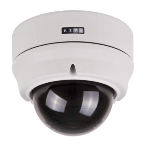
Summary of Contents for RIVATECH RC3512HD-6311
- Page 1 Please access our website and download necessary IPAdminTool first: corresponding connectors on the camera. http://www.rivatech.de/en/downloads/software 5) Prepare the screws (M4x30) with the O-rings inserted. Then, NC3512(63)11-2015-A place the camera body to match the alignment holes with the...
- Page 2 Setting up network environment SETUP page The default IP address of the device is 192.168.XXX.XXX. Users can To setup the device configuraiton: identify the IP address of the device by converting the MAC 1) Click the Setup button on the upper left corner of the web page. address’s hexadecimal numbers.


Need help?
Do you have a question about the RC3512HD-6311 and is the answer not in the manual?
Questions and answers