Table of Contents
Advertisement
Quick Links
phone: 0049(0)2131/7421652 email: info@kvm-discovery.com
Dual Rail AS-7100 & AS-9100 series
LCD KVM User Manual
INTRODUCTION............................................................................................................................................ 2
FEATURES....................................................................................................................................................... 3
PRODUCT TYPE............................................................................................................................................. 4
VIEW OF PRODUCT...................................................................................................................................... 5
FRONT VIEW.......................................................................................................................................... 5
REAR VIEW.............................................................................................................................................6
DIMENSION............................................................................................................................................ 8
KVM SWITCHES PACKING LIST.............................................................................................................. 10
KVM CONTROL PLATFORM CONNECTING WIRE....................................................................... 11
KVM CONTROL PLATFORM POWER WIRE................................................................................... 11
OPERATION.................................................................................................................................................. 12
CONNECTION OF KVM SIGNAL WIRE........................................................................................... 12
Before Use...............................................................................................................................................12
During Use.............................................................................................................................................. 12
After Use................................................................................................................................................. 13
Hot Plug.................................................................................................................................................. 13
Power On/Off and Reboot...................................................................................................................... 13
Assembling & Disassembling.................................................................................................................16
STANDARD RACK INSTALLATION................................................................................................. 18
SINGLE STAGE INSTALLATION....................................................................................................... 20
CASCADE INSTALLATION................................................................................................................ 21
OSD OPERATION......................................................................................................................................... 22
OSD OVERVIEW.................................................................................................................................. 22
OSD NAVIGATION............................................................................................................................... 22
OSD MAIN SCREEN HEADINGS.......................................................................................................23
OSD FUNCTIONS................................................................................................................................. 23
SAFE GUIDE................................................................................................................................................. 26
KVM Discovery
Haitwin-Delphin Technologie GmbH,
Kieselstraße 15, 41472 Neuss / Germany
powered by
1
Advertisement
Table of Contents

Related Manuals for KVM Discovery AS-7100 Series


Summary of Contents for KVM Discovery AS-7100 Series
-
Page 1: Table Of Contents
KVM Discovery powered by Haitwin-Delphin Technologie GmbH, Kieselstraße 15, 41472 Neuss / Germany phone: 0049(0)2131/7421652 email: info@kvm-discovery.com Dual Rail AS-7100 & AS-9100 series LCD KVM User Manual INTRODUCTION............................2 FEATURES............................... 3 PRODUCT TYPE............................. 4 VIEW OF PRODUCT............................5 FRONT VIEW............................5 REAR VIEW.............................6... -
Page 2: Introduction
INTRODUCTION KVM control platform is one with integrate a multiple ports KVM switch into 1U height. It controls multiple computers with one platform (keyboard, mouse and monitor). A KVM switch can control 4/8/16 PC by direct connection and it can control 256 PC at most by 2 level cascade connection. -
Page 3: Features
FEATURES Control Platform Control platform with LCD, keyboard, mouse and multiple ports KVM switch. 1U height, suitable for 19’’ standard cabinet installation and metal structure. 17/19’’ LCD screen with high brightness, high clear and high resolution. With dual rail structure, LCD screen and keyboard can be pulled out separately. ... -
Page 4: Product Type
PRODUCT TYPE Type Function Note AS-7100ULD 17 inches LCD screen, keyboard and mouse. AS-7104/08/16ULD; 17 inches LCD screen, keyboard, mouse and 4/8/16 ports USB KVM. AS-9100ULD 19 inches LCD screen, keyboard and mouse. AS-9104/ 08/16ULD; 19 inches LCD screen, keyboard, mouse and 4/8/16 ports USB KVM . -
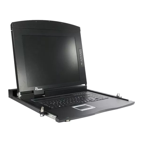
Page 5: View Of Product
VIEW OF PRODUCT FRONT VIEW Handle Lock Front panel LCD screen Rear hang ear channel LCD OSD control key Front hang ear Mouse touch board Guide 10. Lock hole... -
Page 6: Rear View
REAR VIEW AS-7100ULD/AS-9100ULD (with IP module KI-4101) AS-7104ULD/AS-9104ULD (with IP module KI-4101) AS-7108ULD/AS-9108ULD (with IP module KI-4101) AS-7116ULD/AS-9116ULD (with IP module KI-4101) 1 2 3 4 1. IP Module Restore to Default Plug needle or ballpoint pen into the hole to restore the IP module to default setting. 2. - Page 7 If the IP module has no responding, plug needle or ballpoint pen into the hole to reset it. 4. Power Jack The DC 9V~12V power supply cable plugs into this jack. 5. USB Port Ports to plug in your USB keyboard and mouse are found here. 6.
-
Page 8: Dimension
DIMENSION... -
Page 9: Kvm Switches Packing List
KVM SWITCHES PACKING LIST Type Name Num/Unit Note 17 inches LCD screen, keyboard AS-71**Series KVM Control Platform and mouse control platform Products integrated KVM switch with multiple ports (4/8/16ports). 19 inches LCD screen/LCD AS-91**Series KVM Control Platform widescreen, keyboard and mouse Products control platform... -
Page 10: Kvm Control Platform Connecting Wire
KVM CONTROL PLATFORM CONNECTING WIRE Cable Type Applicable Type KVM Port PC or Server Port USB and PS/2 All types VGA port VGA、Keyboard、Mouse Connecting Cable (Keyboard, mouse (Standard USB & PS/2 and monitor) Interface) USB and PS/2 Connecting Cable KVM CONTROL PLATFORM POWER WIRE Wire Type Note Voltage Range... -
Page 11: Operation
OPERATION CONNECTION OF KVM SIGNAL WIRE Before Use Make sure all the devices are safely grounded. Make sure the KVM wire and power wire are connected correctly. During Use Pull the KVM control platform out from cabinet totally, the guide locks automatically and the power turns on. -
Page 12: After Use
Press LCD power key (red), the LCD is on. After Use Press LCD power key, the LCD is power off. Close LCD panel and lock the front panel. Release guide lock. Push the control panel into the cabinet totally, and then it is power off. Hot Plug The KVM control platform supports hot plug. -
Page 13: Structure&Usage
Structure&Usage... -
Page 15: Assembling & Disassembling
Assembling & Disassembling The device can be assembled and disassembled as following. -
Page 17: Standard Rack Installation
STANDARD RACK INSTALLATION Screw the front flange to the rack first. Slide the bars with the rear flange towards the rack until the flanges make contact with the rack, then screw the rear flanges to the rack. 2. Slide the switch onto the support flanges. Use the screws supplied with this package to loosely attach the front of the switch to the front of the rack. - Page 18 4. Use the screws supplied with this package to attach the bars to the rear of the switch.
-
Page 19: Single Stage Installation
SINGLE STAGE INSTALLATION To set up your installation, do the following: 1. Plug your USB / PS/2 keyboard, USB / PS/2 mouse and monitor into the console port section located on the unit’s rear panel. 2. Using a KVM cable set, plug the DB 15 connector into any available CPU port on the switch. -
Page 20: Cascade Installation
CASCADE INSTALLATION To set up cascade installation, do the following: 1. Set up single installation as mentioned in SINGLE STAGE INSTALLATION. 2. Connect one end of HDB15 cable to IN port of upper KVM, and the other end to OUT port of lower KVM. -
Page 21: Osd Operation
OSD OPERATION OSD OVERVIEW The On Screen Display (OSD) is used to handle all computer control and switching procedures. All procedures start from the OSD main menu. To pop up the main menu, tap the [Ctrl] twice. If OSD menu is set as “console locked”, you must input password each time the main menu appears. If no password has been set, just press [Enter] to show main menu. -
Page 22: Osd Main Screen Headings
OSD MAIN SCREEN HEADINGS Heading Explanation This column lists the port numbers for all the CPU ports on the installation. The simplest method to access a particular computer is to move the highlight bar to it, then press [Enter]. If a port has been selected for Quick View scanning, an arrowhead symbol displays in this column to indicate so. - Page 23 main screen with this function. The choices and their meanings are given in the table below: Choice Meaning Lists all of the ports on the installation. QVIEW Lists only the ports that have been selected as Quick View Ports. POWERED ON Lists only the ports that have their attached computers powered on.
- Page 24 Move the highlight bar to an option and press [Enter] to select it. CHANNEL DISPLAY POSITION: Position of the tip window. A small blue window appears on the screen. Use arrow key to move it, then press [Enter] to specify the position.
-
Page 25: Safe Guide
SAFE GUIDE Please follow the directions below when installing, using and maintaining it in order to guarantee the device to work well. When installing and operating the device, please make sure proper power supply first, and then do other operations after it is initialized. ...
Need help?
Do you have a question about the AS-7100 Series and is the answer not in the manual?
Questions and answers