Table of Contents
Advertisement
Quick Links
Advertisement
Table of Contents

Related Manuals for GIGA G4200C


Summary of Contents for GIGA G4200C
- Page 1 G4200C Quick Installation Guide GIGA Copper Networks GmbH...
-
Page 2: Hardware Descriptions
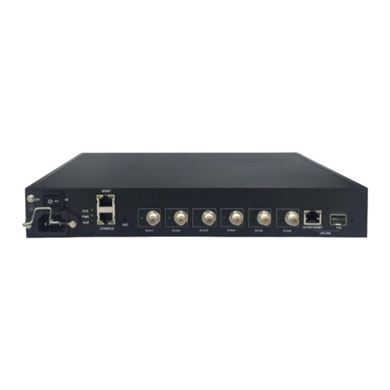
G4200C G4201C 2.1 G4200C (Local device) G4200C is the device of multiplexer system, as shown in the following drawings. It supports one 1000-X/10000-X SFP/SFP+ uplink port, one 10/100/1000BT uplink port, six coax G.hn ports and one gigabit MGMT port. 2.1.1 Panel... - Page 3 The following table shows the port descriptions. Label Description Console port: A RS-232 connector for connection to a computer for console control/administration. The RS-232 console port can be Console used for accessing the device CLI (command line interface) for out-of-band management. MGMT 10/100/1000BT RJ-45 port 10/100/1000BT Ethernet ports...
- Page 4 2.2 G4201C (Remote device) 2.2.1 Panel The panel is shown below: The following table shows the port descriptions. Label Description G.hn input port supporting P2P and P2MP connections LINE 12VDC/1.0A Input Support 12V DC power supply, connect to 12VDC power adapter 10/100/1000BT Ethernet port, Ethernet RJ-45 connection, Connect to computer or other Ethernet device The following table shows the LED description:...
-
Page 5: Hardware Installation
1* power cord. 3.2 Mounting Procedures 3.2.1 Front Mounting on a Standard 19” Rack Using eight bracket screws to fix the mounting brackets on left and right sides close to the front faceplate of G4200C, four bracket screws on each side... - Page 6 If there are screw holes on the rack rail, direct install the rack-mount screws through the holes of the mounting bracket to mount G4200C to the rack, two mounting screws on each side. If there is no screw hole on the rack rail and the holes on the rack rail are square,...
- Page 8 G4200C, four bracket screws on each side If there are screw holes on the rack rail, direct install the rack-mount screws through the holes of the mounting bracket to mount G4200C to the rack, two mounting screws on each side.
- Page 9 G4200C to the rack, two mounting screws on each side.
- Page 10 G4200C, four bracket screws on each side Using 8mm or 3/8” drill tip to drill four holes on the wall with the pattern below Nail in four wall-mount plastic nuts into four drill holes, then mount G4200C on the wall with four wall-mount screws.
- Page 11 Using eight bracket screws to fix the mounting brackets on left and right sides close to the back side of G4200C, four bracket screws on each side Using 8mm or 3/8” drill tip to drill four holes on the wall with the pattern below...
- Page 12 Nail in four wall-mount plastic nuts into four drill holes, then mount G4200C on the wall with four wall-mount screws. 3.3 Connecting Fiber and Coaxial Remove the dust cover on the SFP cage Insert SFP transceiver into the SFP cage...
-
Page 13: Connecting Power
Connect optical fiber to the SFP transceiver and coaxial cable to the G.hn port(s) respectively 3.4 Connecting Power After G4200C has been mounted either on a rack or on the wall and the optical fiber and coaxial cable have been connected properly, please follow the procedures below to power up the system. - Page 14 1. Lift up the power core clip toward the power switch, 2. Plug in the power cord onto power connector, then press down the power core clip 3. Insert the power core to power outlet 4. Switch on the power on the power outlet and on G4200C.
-
Page 15: Application Diagram
4 Application Diagram 5 Service Installation G4200C (Local device) + G4201C, G4204C, G4204C-W (Remote devices) 5.1 G4200C (Local Device) Step 1:Connect to uplink Ethernet port, 10/100/1000BT or 10G If you use CAT5 cable is available, please connect to 10/100/1000BT port. - Page 16 You can browse http://192.168.0.252, input username and password to login WEB interface of G4200C as following: 6.1 Change IP You can configure IP address for G4200C via WEB interface, Click ”VLAN Management” -> “VLAN Interface” from the left menu to configure IP address as following: 6.2 Change Device Time...
- Page 17 6.3 Save Configuration After changing IP address, Device time and others configuration, you need to save configuration through the path Administration >Save Configuration. Otherwise, configuration will be lost once the device is power down or reboot. Check Device Basic Information You can check device basic information through the path System Information>Basic Information.
- Page 18 6.6 Check System Logs You can check system logs through Administration > System Logs > System Logs.
Need help?
Do you have a question about the G4200C and is the answer not in the manual?
Questions and answers