Table of Contents
Advertisement
Quick Links
Advertisement
Table of Contents

Related Manuals for GIGA G4202TCP


Summary of Contents for GIGA G4202TCP
- Page 1 G4202TCP Quick Installation Guide GIGA Copper Networks GmbH...
-
Page 2: Package List
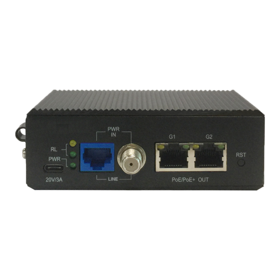
Maximum power consumption: <5w (Without PoE load) 2.2 Front Panel The front panel of the G4202TCP contains 1 *RJ45/F-Type coaxial connector of G.hn port with PoC, 2 *10/100/1000Base-T RJ45 Ethernet port and a USB Type-C connector for extra power supply. -
Page 3: Rear Panel
2.3 Rear Panel 2.4 LED Indicators Stat Label Type Color Description Lights to indicate the power is on Power Status Yellow Indicate the power is off Lights to indicate the coaxial/UTP link is established Green Indicates that the coaxial/UTP link is down Lights to indicate the coaxial/UTP link LINE... -
Page 4: Hardware Specifications
Long Reach POE solution is designed to extend IP Ethernet transmission and inject power into a remote 8.2.3af/at PoE compliant power device (PD) beyond the 100 meters limit of Ethernet. The G4202TCP supports 2 ways as power source to inject 802.3af/at PoE to remote standard PDs (power Devices) ⚫... -
Page 5: Typical Application
Step1. Connect 100-240V AC to the PoC Injector (G4224) Step2. Connect the PoC injector (G4224) and PoE+ extender (G4202TCP) to ends of RJ45 terminated UTP cable, then the G4202TCP will be powered on and the PWR LED will lit up accordingly. - Page 6 Step2. Connect the PoE+ injector (G4224) and PoE+ extender (G4202TCP) via coaxial cable, then the G4202TCP will be powered on and the PWR LED will lit up accordingly. Step3. Connect Cat5/Cat6 UTP cable to G4202TCP and IEEE 802.3af/at complied PoE IP Camera or other PD devices.
- Page 7 G1/G2 RJ45 port with IEEE 802.3af/at PoE output Step1. Connect 100-240V AC to the PoC Injector (G4224) Step2. Connect a 20V/3A DC power to the USB Type-C connector, the G4202TCP will power on and the PWR LED will lit up immediately.
- Page 8 Step1. Connect a 20V/3A DC to the USB Type-C connector (G4202TCP local) Step2. Connect a 20V/3A DC power to the USB Type-C connector (G4202TCP remote), the G4202TCP remote will power on and the PWR LED will lit up immediately. Step3. Connect the G4202TCP (local) and G4202TCP (remote) via UTP cable.
-
Page 9: Mounting Procedures
5. Mounting Procedures The G4202TCP can be mount installed on a chassis/wall, there are 2 hangers on the rear panel of G4202TCP with shipment for mount installation as following picture shows: Rear Panel Hangers for Installation Step1. Remove four mounting fin screws on the back panel as shown below. -
Page 10: Test Condition
Step3. For brick and cement wall, place the G4202TCP to the proper location where it is going to be installed, use a marker or pen to identify the hole locations Step4. Follow the marked hole location, drill four holes using 6mm drill tip and nail in four plastic wall-mount nuts into the holes, then mount the G4202TCP on the wall with four wall-mount screws. - Page 11 6.2 Performance Following charts show the performance and PoE output capability test results in different cable length Throughput(Download/Upload): 802.3af/at/bt PoE Output Mb/s Capability Packet Length:512Bytes Distance Remote Local DC power Local DC (meter) Remote power power through USB power through through F-type through Type-C...
-
Page 12: Appendix A: Rj45 Pin Assignments
40/30 The above PoE output capability results is measured on Ghn11/Ghn12 or Ghn23/Ghn24 of the G4224 which support 802.3bt PoE output, also the G4202TCP support 802.3bt PoE input. Note: The actual data rate will vary on the quality of the copper wire and environment factors.
Need help?
Do you have a question about the G4202TCP and is the answer not in the manual?
Questions and answers