Table of Contents
Advertisement
Quick Links
Revisions ........................................................................................................................................... 1
1 Specifications ................................................................................................................................. 2
1.1 Performance Parameter ....................................................................................................... 2
1.2 Indicator .............................................................................................................................. 4
1.3 Dimensions.......................................................................................................................... 4
1.4 Standard flange ................................................................................................................... 5
1.5 Pinout Description ............................................................................................................... 5
1.6 Product list .......................................................................................................................... 6
2 Modbus-RTU Control .................................................................................................................... 8
2.1 Debugging software description ......................................................................................... 8
2.1.1 Installation and wiring of debugging software ......................................................... 8
2.1.2 Debugging software instructions .............................................................................. 9
2.2 Default Communication Parameters ................................................................................. 12
2.3 Modbus-RTU Description ................................................................................................. 13
2.3.1 RTU Framing ......................................................................................................... 13
2.3.2 Supported Modbus Function Code ......................................................................... 13
2.3.3 Register Mapping ................................................................................................... 13
2.3.4 Register Description ............................................................................................... 15
2.3.4.1 Initialization ................................................................................................ 15
2.3.4.2 Force ............................................................................................................ 15
2.3.4.3 Position ........................................................................................................ 16
2.3.4.4 Speed ........................................................................................................... 16
2.3.4.5 Initialization State ....................................................................................... 17
2.3.4.6 Gripper State ............................................................................................... 17
2.3.4.7 Current Position .......................................................................................... 18
2.3.4.8 Save Parameter ............................................................................................ 18
2.3.4.9 Initialization Direction ................................................................................ 19
2.3.4.10 Slave Address ............................................................................................ 19
2.3.4.11 Baud Rate .................................................................................................. 20
2.3.4.12 Stop Bits .................................................................................................... 20
2.3.4.13 Parity ......................................................................................................... 20
2.3.4.14 Test I/O Parameters ................................................................................... 21
2.3.4.15 I/O Mode Switch ....................................................................................... 21
2.3.4.16 I/O Parameter Configuration ..................................................................... 22
3 I/O Control ................................................................................................................................... 24
Tel/Fax: 0755-82734836
PGC-140 Gripper
Short Manual
Content
www.dh-robotics.com
Advertisement
Table of Contents

Related Manuals for Trossen Robotics PGC Series

Summary of Contents for Trossen Robotics PGC Series
-
Page 1: Table Of Contents
Tel/Fax: 0755-82734836 www.dh-robotics.com PGC-140 Gripper Short Manual Content Revisions ............................1 1 Specifications ..........................2 1.1 Performance Parameter ....................... 2 1.2 Indicator ..........................4 1.3 Dimensions.......................... 4 1.4 Standard flange ........................5 1.5 Pinout Description ....................... 5 1.6 Product list .......................... 6 2 Modbus-RTU Control ........................ -
Page 2: Revisions
Tel/Fax: 0755-82734836 www.dh-robotics.com Revisions Date Version Revised content First edition, write wiring instructions and 20200426 V1.0 command instructions Change some instructions , Update the description 20200904 V2.0 of IO mode 20210401 V2.1 Normal update... -
Page 3: Specifications
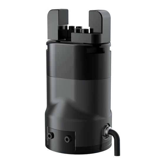
1 Specifications PGC series are collaborative electric gripper, The number(PGC-number) represents the maximum gripping force of the gripper. The gripper is equipped with a pair of parallel fingertips, which runs symmetrically during the movement. The main structure of the gripper is a smooth rectangular structure. - Page 4 Tel/Fax: 0755-82734836 www.dh-robotics.com Table 1.1 PGC-140 specifications PGC-140 performance parameters. Gripping force (per jaw) 40-140N Opening/closing stroke (both sides) 0-50mm Opening/Closing time 0.6s/0.6s Weight 1 kg Position repeatability (both sides) ± 0.03mm Noise emission < 50 dB Ingress protection rating IP54 Communication protocols Modbus RTU(RS485), I/O...
-
Page 5: Indicator
Tel/Fax: 0755-82734836 www.dh-robotics.com 1.2 Indicator The gripper can feed back the state of the gripper in real time. In addition to the command reading, it can also be judged on the color of the indicator: Color description of indicator ·Uninitialized state: Red light blinks, other lights are off. ·Initialized State: the blue light is always on, indicating that it is in the operable state. -
Page 6: Standard Flange
Tel/Fax: 0755-82734836 www.dh-robotics.com 1.4 Standard flange The flange is used for the connection between PGC-140 electric gripper and robot. The company provides standard flange, as shown in Figure 1.4. The gripper also supports custom flanges. Figure 1.4 Standard flange according to ISO 9409-1-50-4-M6 1.5 Pinout Description The pinout of the gripper is shown in Figure 1.5, and the pin description is shown in Table 1.3. -
Page 7: Product List
Tel/Fax: 0755-82734836 www.dh-robotics.com 1.6 Product list After opening the package, please check the product list carefully: Table 1.4 product list number type name quantity gripper PGC gripper flange flange U-disk U-disk Screw M6*12 Thin head screw M4*6 Wrench M2.5 Installation tools Wrench M4 Pin 6*10... - Page 8 Tel/Fax: 0755-82734836 www.dh-robotics.com Figure 1.7 Connecting robot terminal with M8 aviation plug-in cable When adopting this scheme, we need to confirm the pin definition with the robot manufacturer, and confirm the claw outlet according to the pin definition. If the non-standard plug and custom outlet mode are adopted, the extra cost needs to be discussed.
-
Page 9: Modbus-Rtu Control
Tel/Fax: 0755-82734836 www.dh-robotics.com 2 Modbus-RTU Control 2.1 Debugging software description The debugging software is specially used to control the gripper and set debugging parameters on the computer. Because there is no RS485 interface in the computer, the USB to 485 module is needed to convert the interface to USB interface, which is convenient for the debugging and control of the gripper in the computer. -
Page 10: Debugging Software Instructions
Tel/Fax: 0755-82734836 www.dh-robotics.com Wiring instructions ·① : when the device (computer) has RS485 interface, the communication can be directly connected to RS485_A and RS485_B communication lines without transferring to 485 module through USB ·② : in this way, other serial port debugging software (such as MODBUS poll) can be used for debugging Software can be downloaded on the official website. - Page 11 Tel/Fax: 0755-82734836 www.dh-robotics.com (see 2.1.1 Installation and wiring of debugging software). Open the software, the software will automatically identify the serial port, baud rate, ID number and other information of the gripper for automatic connection. As shown in the figure below: Figure 2.3 main control interface The specific interface description is as follows: Interface description...
- Page 12 Tel/Fax: 0755-82734836 www.dh-robotics.com Figure 2.4 View If there are multiple 485 devices, sometimes the baud rate and ID number of the gripper need to be modified, the parameters can be modified in Modbus RTU parameters Figure 2.5 Modbus RTU parameters You can set and configure the gripper I / O parameters in [I / O parameters].
-
Page 13: Default Communication Parameters
Tel/Fax: 0755-82734836 www.dh-robotics.com Figure 2.6 Modbus RTU parameters The steps of switching IO are as follows: Steps to switch IO mode ·① Open IO mode: open IO mode first. ·② Configure four groups of IO parameters: set the four groups of parameters of gripper, including position, force and speed. -
Page 14: Modbus-Rtu Description
Tel/Fax: 0755-82734836 www.dh-robotics.com 2.3 Modbus-RTU Description 2.3.1 RTU Framing This gripper uses the standard Modbus-RTU protocol. In RTU mode, the first field is the device address. The allowable characters transmitted for all fields are hexadecimal 0 ... 9, A ... F. Networked devices monitor the network bus continuously, including during the silent intervals. - Page 15 Tel/Fax: 0755-82734836 www.dh-robotics.com Basic control registers: initialization, force setting, reference position, speed, and some states. Configuration registers: gripper’s parameter configuration. Includes Modbus communication parameters and I/O parameters. Table 2.2 Basic Control register map address Function Description Write Read (hexadecimal) 0x01: Initialize the Initialization initialization;0xA5:...
-
Page 16: Register Description
Tel/Fax: 0755-82734836 www.dh-robotics.com 2.3.4 Register Description 2.3.4.1 Initialization This register is used to initialize the gripper. Write: If write 1 (0x01 hex) to this register, the gripper will be initialized (fingers move to the minimal or maximum position. The initialization direction depends on the value of initialization direction register). -
Page 17: Position
Tel/Fax: 0755-82734836 www.dh-robotics.com Return: 01 06 01 01 1E 59 FE Read the force currently set (read): Send: 01 03 01 01 00 01 D4 36 Return: 01 03 02 xx xx crc1 crc2 2.3.4.3 Position This register is used to set the reference position of gripper's fingers, then the fingers will move to the position immediately. -
Page 18: Initialization State
Tel/Fax: 0755-82734836 www.dh-robotics.com Read the current speed (read): Send: 01 03 01 04 00 01 C4 37 Return: 01 03 02 xx xx crc1 crc2 2.3.4.5 Initialization State This register is used to store current initialization state of gripper, you can get the initialization state by reading this register. -
Page 19: Current Position
Tel/Fax: 0755-82734836 www.dh-robotics.com Send: 01 03 02 01 00 01 D4 72 Return: 01 03 02 00 02 39 85(02: object caught) 2.3.4.7 Current Position This register is used to store the actual position of the Gripper. The address is 0x0202. The description of this register is shown in Table 2.10. Table 2.10 Current Position Function Address... -
Page 20: Initialization Direction
Tel/Fax: 0755-82734836 www.dh-robotics.com 2.3.4.9 Initialization Direction This register is used to set Initialization Direction of gripper. The address is 0x0301. The description of this register is shown in Table 2.12. Table 2.12 Baud Rate Function Address Description Write Read Configure 0: Open,1:Close Baud Rate 0x0301... -
Page 21: Baud Rate
Tel/Fax: 0755-82734836 www.dh-robotics.com 2.3.4.11 Baud Rate This register is used to set Baud Rate of gripper. The address is 0x0303. The description of this register is shown in Table 2.14. Table 2.14 Baud Rate Function Address Description Write Read 0-5:115200,57600, Configure gripper Baud Rate 0x0303... -
Page 22: Test I/O Parameters
Tel/Fax: 0755-82734836 www.dh-robotics.com 0: None Parity Configure 1: Odd Parity Parity 0x0305 gripper Modbus Current setting 2: Even Parity Parity (default : 0) The value of this register is 0 by default, corresponding to None Parity. Example: Set the gripper’s Parity to None Parity (write): Send: 01 06 03 05 00 00 99 8F Return: 01 06 03 05 00 00 99 8F... -
Page 23: I/O Parameter Configuration
Tel/Fax: 0755-82734836 www.dh-robotics.com Table 2.19 Control method Switch State Description Modbus-RTU control mode off control mode on Example: Set the I/O control mode switch off (write): Send: 01 06 04 02 00 00 29 3A Return: 01 06 04 02 00 00 29 3A NOTE ·If you just need to control the gripper through Modbus RTU, you should write 0 to this register and save all parameters to turn off the I/O control mode. - Page 24 Tel/Fax: 0755-82734836 www.dh-robotics.com Return: 01 06 04 06 00 1E E8 F3 Send: 01 06 04 07 00 1E B9 33 (Speed: 30%) Return: 01 06 04 07 00 1E B9 33 IO parameter address is continuous address, and four groups of IO parameters can be configured at one time by using the function code of 0x10, as follows: Continuous multiple address write(write)[Group 1:1000 ‰...
-
Page 25: O Control
Tel/Fax: 0755-82734836 www.dh-robotics.com 3 I/O Control The I/O mode is a common control method in industry. The grippers will monitor the pin states of Input 1 and Input 2 (0V and high resistance states). For these two pins, there will be four logic states:00,01,10,11. You can control this gripper through changing the states of Input 1 and Input 2. - Page 26 Tel/Fax: 0755-82734836 www.dh-robotics.com Table 3.1 Input State INPUT 1 INPUT 2 Pin state Perform action I/O state Target position 1,target No wiring No wiring Group 1 force 1,target speed 1 Target position 2,Target No wiring Group 2 Force 2,Target Speed 2 Target position 3,Target No wiring Group 3...
Need help?
Do you have a question about the PGC Series and is the answer not in the manual?
Questions and answers