Advertisement
Quick Links
WWW.HUNDREDFIT.COM
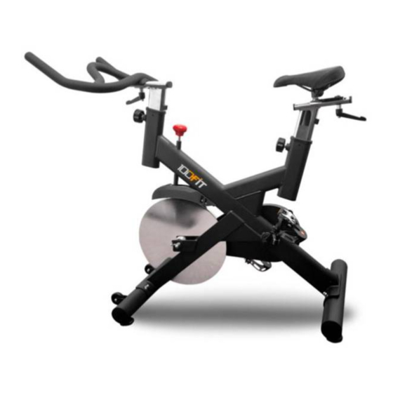
OWNER'S MANUAL (150S)
CONTENTS-----
IMPORTANT INFORMATION -----1-2
ASSEMBLY INSTRUCTIONS-----5-6
COMPLETE EXPLOSION DRAWING -----7
PARTS LIST----8-9
Advertisement

Related Manuals for 100FIT 150S


Summary of Contents for 100FIT 150S
-
Page 1: Table Of Contents
WWW.HUNDREDFIT.COM OWNER'S MANUAL (150S) CONTENTS----- IMPORTANT INFORMATION -----1-2 EXPLODED-VIEW ASSMEBLY DRAWING-----3 ASSEMBLY TOOLS&NECESSARY PARTS -----4 ASSEMBLY INSTRUCTIONS-----5-6 COMPLETE EXPLOSION DRAWING -----7 PARTS LIST----8-9... -
Page 2: Important Information
IMPORTANT INFORMATION SAFETY 1. Please keep this manual in a safe place for your reference when necessary. 2. Please do not assembly or use this equipment until you read this manual thoroughly & carefully. The safety and efficiency only can be achieved when the equipment is assembled, maintained and used properly. - Page 3 coming from the equipment during use, stop immediately. Do not use the equipment until the problem has been solved. 14. Care must be taken when lifting or moving the equipment so as not to injure your back. Always use proper lifting techniques and /or seek assistance if necessary.
-
Page 4: Exploded-View Assmebly Drawing
EXPLODED-VIEW ASSMEBLY DRAWING... -
Page 5: Assembly Tools&Necessary Parts
ASSEMBLY TOOLS&NECESSARY PARTS Washer (Φ 8) Nut (M8) Bolt Hex wrench Spanner... -
Page 6: Assembly Instructions
ASSEMBLING INSTRUCTIONS Step 1 Screw the 4sets of stabilizer adjusting pads(64) onto the two stabilizers (66)&(55) properly first. Attach the rear stabilizer(66) to the main frame (1) and fix it with two sets of domed nuts(63), washers(62) and bolts (61) tightly by spanner. --Then attach the front stabilizer(55) which is with transportation wheels to the main frame (1) and fix it with... - Page 7 Step 3 Insert the saddle post(45) into the main frame (1) as shown after loosening and pulling out the adjusting knob(19),and then select a desired height to align the hole,and then fix it tightly by the adjusting knob(19). --Fix the seat (52) on the post of the seat sliding set(49)properly by spanner.
-
Page 8: Complete Explosion Drawing
COMPLETE EXPLOSION DRAWING... -
Page 9: Parts List
PARTS LIST NAME SPECIFICATION QUANTITY main frame bearing 6001RS flywheel φ425×15T bearing 6004-2RS Flywheel axis φ15×119/M12×P1.25 M12×1.25×7H belt 3PL 1210 Adjusting bolt D12.5-thread40 washer φ13×φ20×2T Domed nut M12×1.25 Crank axis& belt pulley φ20×172L Belt pulley 3PL φ200 bolt M8×14 M8×1.25 Spring washer D8.2 Circlip spacer... - Page 10 M10×1.25×7.5H Inner chain cover screw ST4.2×16 Outer chain cover screw ST4.2×16 Brake cover screw M5×10 Crank cover Seat support post Stop block 20×20×12 PP screw M5×12 Tube plug Seat sliding set Curved block 45X40 T=4.0 L adjusting knob M10×1.5 seat Handle bar Handle bar support post Front stabilizer...