Advertisement
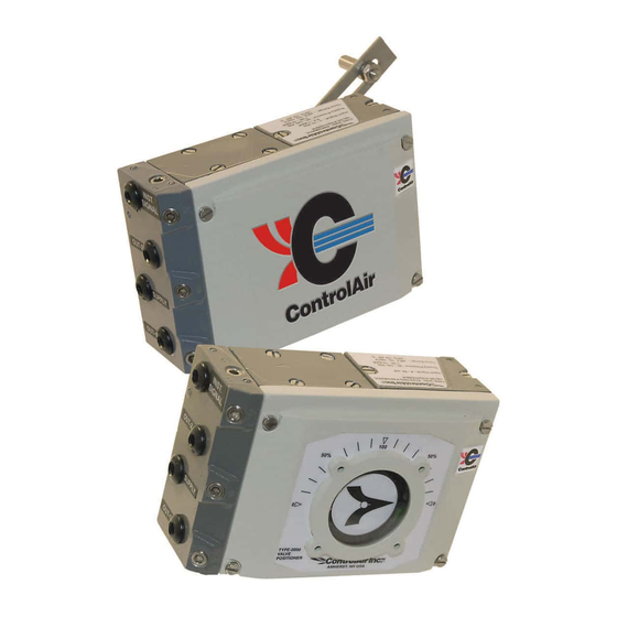
Type 2000
Ordering Information
Use this coding system to order
•
Type of
Motion
R Rotary
L Linear
CA20 -
-
-
Model
Type of Positioner
Spindle
0 Namur (Rotary)
00 P/P Pneumatic
1 Standard (Linear)
2 3/8" Square
3 1/2" Square
11 E/P Electro-pneumatic;
FM/CSA Intrinsically Safe
20 E/P Electro-pneumatic;
ATEX Intrinsically Safe
21 E/P Electro-pneumatic;
FM/CSA Explosion-proof
ATEX Flame-proof
Accessories
Gauges 0-30 psi (0-2 bar), 1/8" NPT Back Mount
0-160 psi (0-11 bar), 1/8" NPT Back Mount P/N: 446-725-008
0-30 psi (0-2 bar), 1/8" NPT Bottom Mount P/N: 446-725-033
441-622-119
Pneumatic and Electropneumatic
Valve Positioner
Installation, Operation and
Maintenance Instructions
•
Cam
C1 90˚/180˚ (Standard Rotary)
C2 45˚/90˚
C3 30˚/60˚ (Standard Linear)
-
-
Indicator
N None
A Arrow
(Standard Linear)
D Dome
(Standard Rotary)
(Option)
P/N: 446-725-006
Contents
Section
Description
1.0
Introduction
2.0
2.3
Approvals
3.0
4.0
5.0
6.0
8 Columbia Drive
Amherst, NH 03031 USA
603-886-9400
Fax: 603-889-1844
www.controlair.com
sales@controlair.com
Type 2000
Page
2
3
4
4
9
10
10
Page 1
Advertisement
Table of Contents

Summary of Contents for controlair 2000
-
Page 1: Table Of Contents
Pneumatic and Electropneumatic Type 2000 Valve Positioner Installation, Operation and Maintenance Instructions Ordering Information Contents Use this coding system to order • • Section Description Page Type of Introduction Motion C1 90˚/180˚ (Standard Rotary) Specifications R Rotary C2 45˚/90˚ L Linear C3 30˚/60˚... - Page 2 1.2 Principles of Operation The Type 2000 operates on a force balance principal of operation. Force is created by the input signal pressure acting on the diaphragm (1) which transmits to the balance arm (2). An opposing force is created by the feedback spring (3) and works in the opposite direction on the balance arm (2).
-
Page 3: P Electro-Pneumatic; Fm/Csa Intrinsically Safe
1.3 Air Requirements 1.3.1 Supply air should be clean, dry, oil-free instrument air filtered to 40 micron. A filter regulator is recommended to be installed as close to the Type-2000 as possible. 1.3.2 Maximum supply pressure is 150 psig (10 bar). -
Page 4: Installation
Failure to do this may result in damage or personal injury. DANGER Do not exceed the positioner performance limitations! Exceeding the limitations marked on the positioner may cause damage to the positioner, actuator and valve. Damage or personal injury may result. 441-622-119 Type 2000 Page 4... - Page 5 Ø 1.7" (Ø 43.5 mm) NOTE Liquid sealant for threads, Loctite or similar, is recommended for all air connections. NOTE The I connection must be plugged in CA2000. The I connection should be plugged in CA2000. 441-622-119 Type 2000 Page 5...
- Page 6 3.3.1 Rotary Actuator The ControlAir Type-2000 has a very stable and properly sized drive shaft bearing. However, the positioner drive (A) should be aligned properly to the rotary actuator spindle (B). A relatively small error combined with a rigid coupling can create very powerful radial forces, which can in turn overload and in short time wear out even the very best drive shaft bearing.
- Page 7 3.4 Cam Adjustment NOTE The ControlAir Type-2000 is standard shipped with the C1-cam, factory set for 90° ±1°, direct (CCW) turning. 3.4.1 Adjustments Loosen and remove the front cover and indicator. 1 Loosen the screw (1) and the cam lock nut (2) by turning counter clockwise.
- Page 8 3.6 Calibration ZERO NOTE >0< The ControlAir Type-2000 is delivered factory calibrated 0 -100% for 90 + 1.0 degree rotation. Calibration procedure Zero Set 0% input signal (3 psi/0.2 bar or 4 mA). Wait until the valve has settled.
-
Page 9: Dimensions
9 23/32 [247] 2 1/4 [57] 5/16-18 1 13/32 [36] 5/16 [7.9] Deep (4) Places 1 7/8 [47] 2 1/4 [57] 1 13/32 [36] Optional Explosion-proof M6x1 11/32 [8.5] Deep 2 3/4 [70] (4) Places 441-622-119 Type 2000 Page 9... -
Page 10: Parts
6. WARRANTY & DISCLAIMER ControlAir, Inc. products are warranted to be free from defects in materials and workmanship for a period of eighteen months from the date of sale, provided said products are used according to ControlAir, Inc. recommended usages. ControlAir, Inc.’s liability is limited to the repair, purchase price refund, or replacement in kind, at ControlAir, Inc.’s sole option, of any products proved defective.


Need help?
Do you have a question about the 2000 and is the answer not in the manual?
Questions and answers