Table of Contents
Advertisement
Quick Links
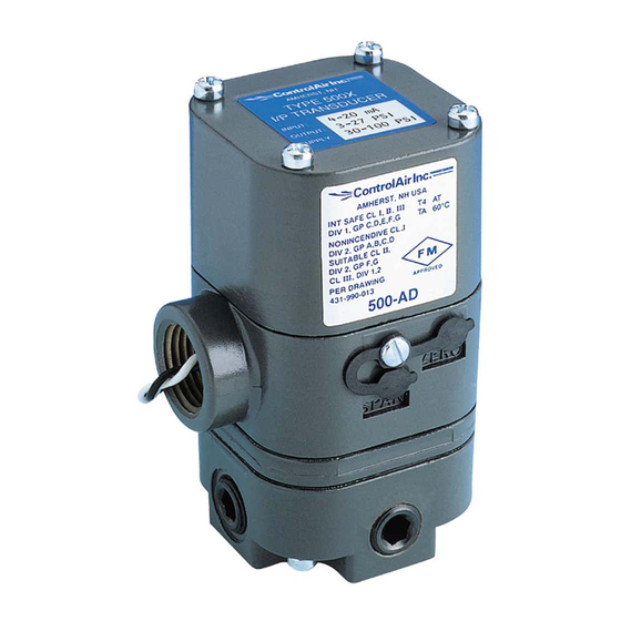
Type 500X
Ordering Information
Type 500X I/P Transducers
Part Number
Input
Type 500X E/P Transducers
Part Number
Input
441-622-015
Electropneumatic Transducer (I/P, E/P)
Installation, Operation and
Maintenance Instructions
Output Range
psi
bar
Impedance
Output Range
psi
bar
Impedance
Pilot Pressure
Atmospheric Pressure
1.0
2.0
3.0
4.0
5.0
8 Columbia Drive / Amherst, NH 03031 USA
Website: www.controlair.com
Email: sales@controlair.com
603-886-9400
An ISO-9001:2008 Certified Company
Type 500X
Supply Pressure
Output Pressure
Description & Installation
2
Operation
Maintenance
Troubleshooting
Warranty
FAX 603-889-1844
Page 1
3
5
5
5
Advertisement
Table of Contents

Related Manuals for controlair 500 Series


Summary of Contents for controlair 500 Series
- Page 1 Type 500X E/P Transducers Description & Installation Output Range Operation Part Number Input Impedance Maintenance Troubleshooting Warranty 8 Columbia Drive / Amherst, NH 03031 USA Website: www.controlair.com Email: sales@controlair.com 603-886-9400 FAX 603-889-1844 An ISO-9001:2008 Certified Company 441-622-015 Type 500X Page 1...
-
Page 2: Danger, Warning, Caution And Note Statements
DANGER, WARNING, CAUTION and NOTE statements DANGER Refers to conditions or hazards which could result in serious personal injury or death. WARNING Refers to conditions or hazards which could result in personal injury. CAUTION Refers to conditions or hazards which could result in equipment or property damage. NOTE Alerts you to facts or special instructions. -
Page 3: Pneumatic Connections
1.4 Pneumatic Connections WARNING The I/P transducer enclosure contains aluminum and is considered to constitute a potential risk of ignition by impact or friction and must be taken into account during installation. 1.5 Electrical Connections Figure 1 DIN 43650 Connector 2. -
Page 4: Dimensional Drawings
2.2 Dimensional Drawings (2) #10-32 UNF-2A x .38 DP. 2.88 1.10 Mounting Holes (Shown with 73.1 27.9 Bracket Screws Installed) 2.18 1.13 Removable 55.4 28.7 14.0 Mounting Max (Square) Bracket Diameter 1.13 1.15 MNTG. 28.7 29.2 Holes Diameter 4.24 107.7 1.04 1.12 1.250... -
Page 5: Maintenance
5.WARRANTY & DISCLAIMER ControlAir, Inc. products are warranted to be free from defects in materials and workmanship for a period of eighteen months from the date of sale, provided said products are used according to ControlAir, Inc. recommended usages. ControlAir, Inc.’s liability is limited to the repair, purchase price refund, or replacement in kind, at ControlAir, Inc.’s sole option, of any products proved defective.
Need help?
Do you have a question about the 500 Series and is the answer not in the manual?
Questions and answers