
Related Manuals for Muir STORM VR 2500


Summary of Contents for Muir STORM VR 2500
- Page 1 T H E W O R L D P O W E R A N C H O R I N G S Y S T E M S STORM VR / VRC 2500/3500/4000 VERTICAL WINDLASS 23/12/2014 www.muir.com.au...
-
Page 2: Table Of Contents
Wiring Diagram for 12/24V DC three terminals 1200W, 1500W motor Wiring Diagram for 12/24V DC four terminals 2000W motor Water Protection Diagram Gearbox Part List Exploded View of VR2500/3500 Storm Exploded View of VR4000 Storm (MORS) Exploded View of VRC2500/3500 Storm Exploded View of VRC4000 Storm (MORS) 23/12/2014 www.muir.com.au... -
Page 3: Introduction
S Y S T E M S INTRODUCTION Thank you for purchasing a Muir Windlass. Muir go to great lengths to develop anchoring systems that not only meet all your performance and safety requirements, but at the same time designed with a style and finish that enhances the aesthetics of your vessel. - Page 4 7. Place washers and bolt in the end of the shaft and tighten / Fit circlip. NOTE: On assembly, grease all moving parts and deck plate grease nipple with a Lithium/teflon based grease. The Motor/geardrive assembly should be protected with anti-corrosion film or grease tape. 23/12/2014 www.muir.com.au...
-
Page 5: Depth Of Chain Locker
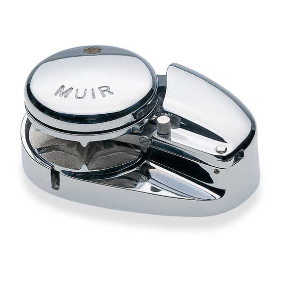
Vertical windlasses minimise deck intrusion and the modern curved lines of the Muir windlass enhance the look of any vessel. A vertical windlass provides the advantages of a I80-degree wrap of the anchor rode around the gypsy. -
Page 6: Handy Hints
This way up WINCH MODEL MOTOR SIZE MOTOR TYPE VR/C 2500 1200 W 3 POLE VR/C 3500 1500 W 3 POLE VR/C 4000 2000 W 4 POLE 2/4 POLE SOLENOID WARNING: Keep solenoid away from salt and fresh water 23/12/2014 www.muir.com.au... -
Page 7: Wiring Layout
REMOTE SW ITCH REMOTE / DECK SWITCH LAYOUT BATTERY CIRCUIT BREAKER SOLENOID/CONTROL BOX DECK SW ITCHES REMOTE SWITCH AUTO ANCHOR LAYOUT BATTERY CIRCUIT BREAKER SOLENOID/CONTROL BOX DECK SWITCHES AUTO ANCHOR AUTO ANCHOR SENSOR NOT TO BE USED AS WIRING DIAGRAMS 23/12/2014 www.muir.com.au... -
Page 8: Operation
Work and Charter Vesels we suggest it is carried out more frequently. Do not use soap based grease. Gradually loosen Tighten to brake the to release the line outgoing line manually Fully tighten retrieve the anchor under power 23/12/2014 www.muir.com.au... -
Page 9: Gypsy Changing And Or Maintenance
Before re-assembly, grease the exposed Main Shaft/cone & Gypsy bore. • The Windlass Base Plate can be greased via grease nipple located at the rear of the base. • The Motor / geardrive assembly should be protected with anti-corrosion film or grease tape. • 23/12/2014 www.muir.com.au... -
Page 10: Rope Chain Management System Adjustment
Line Care Using the wrong type of line may cause the line to jam causing excessive line wear. Muir Windlasses are designed to run on 3-strand nylon line (supplied by Muir) which has been specially treated with fabric softener to prevent it from hardening. -
Page 11: Manual Override System (Mors)
8. Remove the pawls and replace them into the adjacent slots taking care not to loose the pawl springs 9. To reassemble the winch, repeat steps 1 – 9 in reverse order Note: The ratchet pawl assembly is disengaged when assembled at Muir engineering Pty Ltd. 23/12/2014... -
Page 12: Troubleshooting
3. Check the drive key on main shaft to gearbox output. 4. Check the drive key between the gearbox and motor input. HYDRAULIC MOTOR Refer any problems with your hydraulic motor to a Muir service agent or Muir Hobart. WATER PROTECTION DIAGRAM NOTE:... -
Page 13: Maintenance Schedule
2 years after installation – see page 9 Remove chain wheel, clean cones then fully grease and lubrication. 3 years after installation – see page 9 4 years after installation Full winch Service 23/12/2014 www.muir.com.au... - Page 20 GEARBOX PARTS REFERENCE Item Description Gearbox Winch Item Description Gearbox Winch Housing—integrated Flange 44-49 VR/C500-850-1000-1200-1250 Housing VR/C2500-3500 Wormwheel 44-49-63 VR/C500-850-1000-1200-1250 Motor flange VR/C2500-3500 Wormshaft 44-49-63 VR/C500-850-1000-1200-1250 Gasket VR/C2500-3500 Gasket 44-49-63 VR/C500-850-1000-1200-1250 Hex Head Screw VR/C2500-3500 Bearing 44-49-63 VR/C500-850-1000-1200-1250 Bearing 44-49-63 VR/C500-850-1000-1200-1250 Socket Head Screw VR/C2500-3500...
- Page 29 T H E W O R L D P O W E R A N C H O R I N G S Y S T E M S NOTES www.muir.com.au...
- Page 30 • Normal worn parts or to damage caused by neglect, lack of maintenance, accident or improper service/installation or service by persons other than an authorised Muir representative. • Muir shall not be responsible for failures due to products being used in applications that they are not intended for, or exceed the products performance specifications.
- Page 31 THIS PAGE INTENTIONALLY LEFT BLANK...
- Page 32 SERIAL NUMBER © 2005 Muir Engineering Pty. Ltd. Muir reserves the right to alter specifications without notice. All rights reserved. While all due care and attention has been taken in the preparation of this manual no responsibility shall be taken for errors or omissions.
Need help?
Do you have a question about the STORM VR 2500 and is the answer not in the manual?
Questions and answers