Table of Contents
Advertisement
Type A1SCPUC24-R2/A1SHCPU/
A2SHCPU(S1)/A2ASCPU(S1/S30)/
Mitsubishi Programmable Controller
Thank you for purchasing the Mitsubishi programmable controller
MELSEC-A series.
Prior to use, please read both this and relevant manuals thoroughly
to fully understand the product.
© 1994 MITSUBISHI ELECTRIC CORPORATION
A2USHCPU-S1
User's Manual
A1S/A2S/A2ASCPU
MODEL
MODEL
CODE
IB(NA)-66468-R(1112)MEE
(Hardware)
(H/W)-U-E
13JE59
Advertisement
Table of Contents

Related Manuals for Mitsubishi MELSEC-A A1SCPUC24-R2


Summary of Contents for Mitsubishi MELSEC-A A1SCPUC24-R2
- Page 1 Type A1SCPUC24-R2/A1SHCPU/ A2SHCPU(S1)/A2ASCPU(S1/S30)/ A2USHCPU-S1 Mitsubishi Programmable Controller User's Manual (Hardware) Thank you for purchasing the Mitsubishi programmable controller MELSEC-A series. Prior to use, please read both this and relevant manuals thoroughly to fully understand the product. A1S/A2S/A2ASCPU MODEL (H/W)-U-E MODEL...
- Page 3 SAFETY PRECAUTIONS (Read these precautions before using this product.) Before using this product, please read this manual and the relevant manuals carefully and pay full attention to safety to handle the product correctly. In this manual, the safety precautions are classified into two levels: "...
- Page 4 [DESIGN PRECAUTIONS] WARNING (2) When the programmable controller detects the following error conditions, it stops the operation and turn off all the outputs. • The overcurrent protection device or overvoltage protection device of the power supply module is activated. • The programmable controller CPU detects an error such as a watchdog timer error by the self-diagnostics function.
- Page 5 [DESIGN PRECAUTIONS] WARNING When controlling a running programmable controller (data modification) by connecting a peripheral device to the CPU module or a PC to a special function module, create an interlock circuit on sequence programs so that the whole system functions safely all the time. Also, before performing any other controls (e.g.
- Page 6 CAUTION Do not install the control lines or communication cables together with the main circuit or power lines, or bring them close to each other. Keep a distance of 100mm (3.94inch) or more between them. Failure to do so may cause malfunctions due to noise. When an output module is used to control the lamp load, heater, solenoid valve, etc., a large current (ten times larger than the normal one) may flow at the time that the output status changes from OFF to ON.
- Page 7 [INSTALLATION PRECAUTIONS] CAUTION Use the programmable controller under the environment specified in the user’s manual. Otherwise, it may cause electric shocks, fires, malfunctions, product deterioration or damage. Insert the module fixing projection into the fixing hole in the base unit and then tighten the module mounting screw within the specified torque.
- Page 8 [WIRING PRECAUTIONS] WARNING Be sure to shut off all phases of the external power supply used by the system before wiring. Failure to do so may result in an electric shock or damage of the product. Before energizing and operating the system after wiring, be sure to attach the terminal cover supplied with the product.
- Page 9 [STARTUP AND MAINTENANCE PRECAUTIONS] WARNING Do not touch any terminal during power distribution. Doing so may cause an electric shock. Properly connect batteries. Do not charge, disassemble, heat or throw them into the fire and do not make them short-circuited and soldered. Incorrect battery handling may cause personal injuries or a fire due to exothermic heat, burst and/or ignition.
- Page 10 [DISPOSAL PRECAUTIONS] CAUTION When disposing of the product, treat it as an industrial waste. When disposing of batteries, separate them from other wastes according to the local regulations. (For details of the Battery Directive in EU member states, refer to User's manual for the CPU module used.) [TRANSPORTATION PRECAUTIONS] CAUTION...
- Page 12 A-10...
- Page 13 A-11...
- Page 14 A-12...
- Page 15 A-13...
- Page 16 A-14...
- Page 17 A-15...
- Page 18 CONDITIONS OF USE FOR THE PRODUCT (1) Mitsubishi programmable controller ("the PRODUCT") shall be used in conditions; i) where any problem, fault or failure occurring in the PRODUCT, if any, shall not lead to any major or serious accident; and...
- Page 19 PRODUCT in one or more of the Prohibited Applications, provided that the usage of the PRODUCT is limited only for the specific applications agreed to by Mitsubishi and provided further that no special quality assurance or fail-safe, redundant or other safety features which exceed the general specifications of the PRODUCTs are required.
- Page 20 REVISIONS *The manual number is given on the bottom right of the cover. Print Date *Manual Number Revision Apr., 1994 IB (NA) 66468-A First edition Dec., 1994 IB (NA) 66468-B Jun., 1995 IB (NA) 66468-C Oct., 1995 IB (NA) 66468-D Jan., 1996 IB (NA) 66468-E Apr., 1997...
- Page 21 This manual confers no industrial property rights or any rights of any other kind, nor dose it confer any patent licenses. Mitsubishi Electric Corporation cannot be held responsible for any problems involving industrial property rights which may occur as a result of using the contents noted in this manual.
-
Page 22: Table Of Contents
CONTENTS 1. SPECIFICATIONS ..................1 1.1 SPECIFICATIONS ................... 1 2. PERFORMANCE SPECIFICATIONS ............. 3 2.1 Performance Specifications..............3 2.1.1 A1SCPUC24-R2 Module Performance Specifications...... 3 2.1.2 AnSHCPU Module Performance Specifications........ 4 2.1.3 A2ASCPU(S1), A2USHCPU-S1 Module Performance Specifications ......................5 3. EMC DIRECTIVES AND LOW VOLTAGE DIRECTIVES ......7 3.1 Requirements for Compliance with EMC Directives......... - Page 23 4.4 Precautions when Connecting the Uninterruptible Power Supply (UPS) 46 4.5 Part Names..................... 47 4.6 RS232C Interface (A1SCPUC24-R2 only) ..........54 4.7 Self-Loopback Test (A1SCPUC24-R2 only)........... 57 5. SPECIFICATION AND CONNECTION OF I/O MODULES ......58 5.1 Input modules ..................58 5.1.1 Input module specifications.............
- Page 24 This manual describes cautions on handling, connection to I/O modules, and error codes of A2ASCPU(S1/S30), and A1SHCPU, A2SHCPU(S1), A1SCPUC24-R2 (hereafter called "the CPU"). Manuals The following manuals are related to this product. Refer to the following manuals when necessary. Detailed manuals Manual No.
- Page 25 Related manuals Manual No. Manual Name (Model Code) Type ACPU/QCPU-A (A Mode) Programming Manual (Fundamentals) Describes programming methods necessary for creating programs, IB-66249 device names, parameters, program types, memory area (13J740) configuration, and so on. (Optional) Type ACPU/QCPU-A (A Mode) Programming Manual (Common Instructions) IB-66250 Describes how to use the sequence instruction, basic instructions,...
- Page 26 USER PRECAUTONS Precautions when using the AnS series For a new CPU module, which has never used before, the contents of built-in RAM and device data are undefined. Make sure to clear the built-in RAM memory (PC memory all clear) in the CPU module by peripheral devices and operate latch clear by RUN/STOP key switches.
-
Page 27: Specifications
1. SPECIFICATIONS 1.1 SPECIFICATIONS Table 1.1 General specification Item Specifications Operating 0 to 55 °C ambient temperature Storage −20 to 75 °C ambient temperature Operating ambient humidity 10 to 90%RH, non-condensing Storage ambient humidity Constant Half Sweep Frequency acceleration amplitude count 5 to 9Hz 3.5mm... - Page 28 0m. Doing so may cause malfunction. When using the programmable controller under pressure, please consult your local Mitsubishi Electric representative. When an A series extension base unit (A52B, A55B, A58B, A62B, A65B, A68B) is used in the system, the following specifications apply.
-
Page 29: Performance Specifications
2. PERFORMANCE SPECIFICATIONS 2.1 Performance Specifications 2.1.1 A1SCPUC24-R2 Module Performance Specifications The memory capacity, device performances and other specifications of A1SCPUC24-R2 module are provided below. Table 2.1 Performance specifications Type A1SCPUC24-R2 Item Control system Repeated operation (using stored program) I/O control method Refresh mode/Direct mode selectable Language dedicated to sequence control. -
Page 30: Anshcpu Module Performance Specifications
2.1.2 AnSHCPU Module Performance Specifications The memory capacity, device performances and other specifications of AnSHCPU modules are provided below. Table 2.2 Performance specifications Type A1SHCPU A2SHCPU(S1) Item Control system Repeated operation (using stored program) I/O control method Refresh mode/Direct mode selectable Language dedicated to sequence control. -
Page 31: A2Ascpu(S1), A2Ushcpu-S1 Module Performance Specifications
2.1.3 A2ASCPU(S1), A2USHCPU-S1 Module Performance Specifications The memory capacity, device performances and other specifications of A2ASCPU(S1/S30) modules are provided below. Table 2.3 Performance specifications Performance Item Remarks A2ASCPU A2ASCPU A2USHCPU A2ASCPU -S30 Control system Stored program, repeated operation Instructions to enable partial I/O control method Refresh method... - Page 32 Table 2.3 Performance specifications (Continued) Performance Item Remarks A2ASCPU A2ASCPU A2USHCPU A2ASCPU -S30 Output mode Selection of re-output of operation state before Set in switching at STOP → STOP (default)/output after operation execution parameters. Watchdog error timer (watchdog timer 200 ms fixed) Self-diagnostic Refer to Section Memory error detection, CPU error detection, I/O...
-
Page 33: Emc Directives And Low Voltage Directives
(1) Authorized representative in Europe Authorized representative in Europe is shown below. Name: Mitsubishi Electric Europe BV Address: Gothaer Strasse 8, 40880 Ratingen, Germany 3.1 Requirements for Compliance with EMC Directives The EMC Directives specifies emission and immunity criteria and requires the products to meet both of them, i.e., not to emit excessive... -
Page 34: Emc Standards
3.1.1 EMC standards (1) Regulations regarding emission Standard Test item Test description Value specified in standard • 30M-230MHz QP: 40dBµV/m (10m in CISPR16-2-3 Radio waves from measurement range) *1 Radiated emission the product are • 230M-1000MHz measured. QP: 47dBµV/m (10m in EN61131-2: measurement range) 2007... - Page 35 (2) Regulations regarding immunity Standard Test item Test description Value specified in standard Immunity test in EN61000-4-2 which electrostatic Electrostatic • 8kV Air discharge is applied to the discharge immunity • 4kV Contact discharge cabinet of the equipment. EN61000-4-3 Immunity test in 80% AM modulation@1kHz Radiated, radio- which electric fields...
-
Page 36: Installation Instructions For Emc Directive
3.1.2 Installation instructions for EMC Directive The programmable controller is open equipment and must be installed within a control cabinet for use.* This not only ensures safety but also ensues effective shielding of programmable controller-generated electromagnetic noise. Also, each network remote station needs to be installed inside the control panel. - Page 37 (2) Connection of power and earth wires Earthing and power supply wires for the programmable controller system must be connected as described below. (a) Provide an earthing point near the power supply module. Earth the power supply's LG and FG terminals (LG : Line Ground, FG : Frame Ground) with the thickest and shortest wire possible.
-
Page 38: Cables
3.1.3 Cables The cables extracted from the control panel contain a high frequency noise component. On the outside of the control panel, therefore, they serve as antennas to emit noise. To prevent noise emission, use shielded cables for the cables which are connected to the I/O modules and intelligent function modules and may be extracted to the outside of the control panel. - Page 39 A1SJ71AR21, A1SJ71LR21 and A1SJ71BR11. Noise in the range of 30 MHz or higher in radiation noise can be suppressed by the use of double-shielded coaxial cables (manufactured by MITSUBISHI CABLE INDUSTRIES, LTD: 5C-2V-CCY). Earth the outer shield to the ground.
- Page 40 (b) Use shielded twisted pair cables as the twisted pair cables*1 connected to the 10BASE-T connectors. For the shielded twisted pair cables, strip part of the outer cover and earth the exposed shield section to the ground on the widest contact surface as shown below.
- Page 41 (5) Positioning Modules Precautions to be followed when the machinery conforming to the EMC Directive is configured using the A1SD75P -S3 are described below. (a) When wiring with a 2 m (6.56 ft.) or less cable • Ground the shield section of the external wiring cable with the cable clamp.
- Page 42 (c) Ferrite core and cable clamp types and required quantities • Cable clamp Type: AD75CK (manufactured by Mitsubishi Electric Corporation) • Ferrite core Type: ZCAT3035-1330 (manufactured by TDK Corporation) Contact: TDK Corporation • Required quantity Required Qty Cable length Prepared part...
- Page 43 (c) The CC-Link module, the CC-Link stations and the FG line inside the control panel should be connected at the FG terminal as shown in the diagram below. [Simplified diagram] Remote module Local module Master module (Blue) (White) Terminal (Yellow) Terminal resistor resistor...
-
Page 44: Power Supply Module
(7) CC-Link/LT module To supply the CL2DA2-B and CL2AD4-B with 24VDC power using the CL1PAD1, keep the length of the power cable from the CL1PAD1 to the 24VDC power supply to 30m or less. (8) Measures against static electricity When using an insulation displacement connector without connector cover, a connected cable for the connector is thin in applicable wire size and coating. -
Page 45: Ferrite Core
3.1.5 Ferrite core Use of ferrite cores is effective in reducing the conduction noise in the band of about 10 MHz and radiated noise in 30 to 100 MHz band. It is recommended to attach ferrite cores when the shield of the shielded cable coming out of the control panel does not work effectively, or when emission of the conduction noise from the power line has to be suppressed. -
Page 46: Power Line For External Power Supply Terminal
The precautions required when installing a noise filter are described below. (1) Do not bundle the wires on the input side and output side of the noise filter. When bundled, the output side noise will be induced into the input side wires from which the noise was filtered. Input side Input side (power supply side) -
Page 47: Installation Environment Of The Cc-Link/Lt Module And The As-I Module
3.1.8 Installation environment of the CC-Link/LT module and the AS-i module (1) CC-Link/LT module Use the module under the environment of Zone A*1. For the categories of the following products, refer to the manual came with each product. • CL1Y4-R1B1 •... -
Page 48: Requirements For Compliance With Low Voltage Directives
3.2 Requirements for Compliance with Low Voltage Directives The Low Voltage Directives apply to the electrical equipment operating from 50 to 1000VAC or 75 to 1500VDC; the manufacturer must ensure the adequate safety of the equipment. Guidelines for installation and wiring of MELSEC-AnS series programmable controller are provided in Section 3.2.1 to 3.2.7 for the purpose of compliance with the EMC Directives. - Page 49 (2) I/O module For I/O module with rated input voltage of 100/200 VAC, select a model in which the internal area between the first order and second order is intensively insulated, because it has hazardous voltage area. For I/O module with 24 VDC rated input, a conventional model can be used.
-
Page 50: Power Supply
3.2.3 Power supply The insulation specification of the power module was designed assuming installation category II. Be sure to use the installation category II power supply to the programmable controller. The installation category indicates the durability level against surge voltage generated by a thunderbolt. Category I has the lowest durability; category IV has the highest durability. - Page 51 (2) Dustproof and waterproof features The control panel also has the dustproof and waterproof functions. Insufficient dustproof and waterproof features lower the insulation withstand voltage, resulting in insulation destruction. The insulation in our programmable controller is designed to cope with the pollution level 2, so use in an environment with pollution level 2 or below.
-
Page 52: Module Installation
3.2.5 Module installation (1) Installing modules contiguously In QAnS series programmable controllers, the left side of each I/O module is left open. When installing an I/O module to the base, do not make any open slots between any two modules. If there is an open slot on the left side of a module with 100/200 VAC rating, the printed board which contains the hazardous voltage circuit becomes bare. -
Page 53: Loading And Installation
4. LOADING AND INSTALLATION 4.1 Installing the Module 4.1.1 Notes on handling the module This section explains some notes on handling the CPU module, I/O module, special function module, power supply module, and base unit. (1) Do not drop or allow any impact to the modules case, memory card, terminal block cover, or pin connector. -
Page 54: Installation Environment
(6) When installing the base unit to DIN rail in an environment with large vibration, use a vibration-proofing bracket (A1S-PLT-D). Mounting the vibration-proofing bracket (A1S-PLT-D) enhances the resistance to vibration. Depending on the environment to set up the base unit, it is also recommended to fix the base unit to the control panel directly. -
Page 55: Notes On Installing The Base Unit
4.1.3 Notes on installing the base unit Take ease of operation, ease of maintenance, and environmental durability into consideration when you are installing the programmable controller on the panel. (1) Mounting dimension Mounting dimensions of each base unit are as follows: A1S52B A1S55B A1S58B... - Page 56 (2) Module installation position To maintain good ventilation and make it easy to replace the module, keep the following distances between the top and bottom of the module and the structure or other components. • A1S3 B, A1S38HB, A1S38HBEU, A1S5 B(S1), A1S6 B(S1) 30 mm (1.18 inch) or over ..............
- Page 57 (b) Do not use the programmable controller in the following positions: Vertical position Horizontal position (4) Install the base unit on a level surface. If the surface is not level, force may be applied to the printed wiring board, causing a malfunction. (5) Install the unit far from any source of vibration, such as a large magnetic contactor and a no-fuse breaker on the same panel, or install it on a separate panel.
-
Page 58: Fail-Safe Circuit Concept
4.2 Fail-Safe Circuit Concept When the programmable controller is powered ON and then OFF, improper outputs may be generated temporarily depending on the delay time and start-up time differences between the programmable controller power supply and the external power supply for the control target (especially, DC). - Page 59 (1) System design circuit example AC system DC system Power supply Power supply DC power supply Transformer established signal Transformer input Fuse Fuse Start/stop circuit module Can be started CPU module DC power M9006 by turning ON of M9006 supply RA1, which is the M9039 M9039...
- Page 60 The procedures used to switch on the power supply are indicated below. AC system AC/DC system [1] Switch the power supply ON. [1] Switch the power supply ON. [2] Set the CPU module to RUN. [2] Set the CPU module to RUN. [3] Switch the start switch ON.
- Page 61 In such cases, all I/O points turn ON or OFF depending on the problem, and normal operation and safety cannot be maintained. Though Mitsubishi programmable controllers are manufactured under strict quality control, they may fail or malfunction due to unspecified reasons. To prevent the whole system failure, machine breakdown, and accidents, build a fail-safe circuit outside the programmable controller.
- Page 62 Since YB0 turns ON and OFF alternatively at 0.5 second intervals, use a contactless output module (a transistor is used in the above example). If an offdelay timer (especially miniature timer) is not available, construct the failsafe circuit using an ondelay timer shown on the next page.
-
Page 63: Wiring
4.3 Wiring 4.3.1 Power supply module specifications (1) Table 4.1 shows the specifications of the power supply modules. Table 4.1 Power supply module specifications Specifications Item A1S61PN A1S62PN A1S63P Base unit position Power supply module slot 100 to 240 V AC (+ 10 %/-15 %) 24 V DC (+ 30 %/−... - Page 64 POINT Overcurrent protection The overcurrent proctection device shuts off the 5VDC and/or 24VDC circuit(s) and stops the system if the current exceeding the specified value flows in the circuit(s). As this results in voltage drop, the power supply module LED turns OFF or is dimly lit.
-
Page 65: Parts Names
4.3.2 Parts names The following gives the names and description of the parts of the power supply modules : (1) A1S61PN (2) A1S62PN (3) A1S63P Name Description [1] POWER LED The indicator LED for the 5 V DC power. 24 V and 24 G Used to supply 24 V DC to inside the output module terminals (using external wiring). - Page 66 Name Description Power supply Used to connect 100 V AC to 200 V AC power supply. input terminals M3.5 × 7 [7] Terminal screw [8] Terminal cover The protective cover of the terminal block. Module fixing Used to fix the module to the base unit. screw (M4 screw, tightening torque: 78 to 118 N⋅cm) POINT...
-
Page 67: Wiring Instructions
4.3.3 Wiring instructions Instructions for wiring the power supply cable and I/O cable. (1) Wiring of power supply (a) When voltage fluctuations are larger than the specified value, connect a constant-voltage transformer. Constant Programmable voltage controller transformer (b) Use a power supply which generates minimal noise between wires and between the PLC and ground. - Page 68 (e) Taking rated current or inrush current into consideration when wiring the power supply, be sure to connect a breaker or an external fuse that have proper blown and detection. When using a single programmable controller, a 10A breaker or an external fuse are recommended for wiring protection. Programmable Insulation controller...
- Page 69 (h) Do not bind 100VAC and 24VDC wires together with main circuit (high tension and large current) wires or I/O signal lines (including common line) nor place them near each other. Provide 100mm (3.94 inch) clearance between the wires if possible.
- Page 70 (d) When the main circuit line and power line cannot be separated, use a shielding cable and ground it on the programmable controller side. However, ground it on the opposite side in some cases. Programmable controller Shielded cable Input Output Shield jacket (e) When cables are run through pipes, securely ground the pipes.
-
Page 71: Wiring To Module Terminals
4.3.4 Wiring to module terminals This section explains the wiring of power lines and grounding lines to the main and extension bases. Main base unit (A1S38B) Main base unit (A1S38B) 100/110V 00/110 A1S62PN A1S61PN 200/220V 200/220VAC +24V Fuse Fuse (FG) (FG) 24VDC (LG) -
Page 72: Precautions When Connecting The Uninterruptible Power Supply (Ups)
When connecting an uninterruptible power supply (UPS) to the programmable controller system, use an online UPS or line-interactive UPS with a voltage distortion rate of 5% or less. When connecting a standby UPS, use a Mitsubishi FREQUPS FW-F series UPS (hereinafter FW-F series UPS)*1. (Example: FW-F10-0.3K/ 0.5K) Do not use any standby UPS other than the FW-F series UPS. -
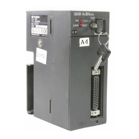
Page 73: Part Names
4.5 Part Names This section gives part names of the CPU. (11) (10) A2ASCPU(S1/S30)/A2USHCPU-S1 (1) RUN/STOP key switch RUN/STOP:Used to start/stop sequence program execution. L.CLR:Used to clear the data set in the latch range set in the parameters. (2) [RUN] LED The RUN/STOP switch is set to "RUN"... - Page 74 (3) [ERROR] LED Self-diagnostic error is detected. (when an error set to OFF is detected by the LED indication priority setting, the switch stays OFF) OFF: When failure of the system or target device is detected by normal or CHK instruction. Flicker: Annunciator (F) is turned on in the sequence program.
- Page 75 (11) Memory write protect Dip switch Setting Switch Memory Write Protect Range A2SHCPU-S1 A2SHCPU (kbytes) A2ASCPU-S1/S30 A2ASCPU A2USHCPU-S1 0 to 16 1: ON 1: ON 16 to 32 2: ON 2: ON 48 to 64 4: ON 4: ON 64 to 80 Unused 5: ON 80 to 96...
- Page 76 (12) (13) (14) (15) A1SCPUC24-R2 (12) Transmission specification setting switch Transmission specification settings (factory setting: all OFF) Position of Setting Switch SW Setting Items Write during RUN enabled/ Enabled Disabled disabled setting Transmission speed setting Refer to *1 Data bit setting 8 bit 7 bit Parity bit setting...
- Page 77 (13) Mode setting switch Mode settings (factory setting: 0) Mode Setting Switch Number Setting Unusable Protocol 1 Protocol 2 Protocol 3 Protocol 4 MODE No-protocol or printer function 6 to E Unusable Used for testing the independent module (14) Computer link LED LED No.
- Page 78 (15) RS-232C connector Refer to the following manual for computer link function. Computer Link/Multidrop unit User's Manual (Computer link/Printer function) SH-3511 (16) (10) A1SHCPU/A2SHCPU(S1)
- Page 79 (16) Dip switch Switch No. Application Memory write protect setting (RAM and E PROM) A1SHCPU ON: With memory write protection *1 OFF: Without memory write protection I/O select switch setting ON: Direct method OFF: Refresh method When installing the memory cassette, the setting becomes invalid to RAM only.
-
Page 80: Rs232C Interface (A1Scpuc24-R2 Only)
4.6 RS232C Interface (A1SCPUC24-R2 only) (1) RS-232C connector specifications Signal Direction Signal Signal Name A1SCPUC24-R2 Number Abbreviation ↔External Device Receive carrier detection RD(RXD) Receive data SD(TXD) Send data DTR(ER) Data terminal ready Signal ground DSR(DR) Data set ready RS(RTS) Request to send CS(CTS) Clear to send A 9-pin D subconnector is supplied in the same package as the... - Page 81 (a) Example connection to an external device in which the CD signal (pin No.8) can be switched ON and OFF. External A1SCPUC24-R2 Cable Device Connections and Signal Signal Signal Directions Names Number Names RD(RXD) RD(RXD) SD(TXD) SD(TXD) DTR(ER) DTR(ER) DSR(DR) DSR(DR) RS(RTS) RS(RTS)
- Page 82 2) Example connection to an external device in which DC code control is executed. External A1SCPUC24-R2 Cable Device Connections and Signal Signal Signal Directions Names Number Names RD(RXD) RD(RXD) SD(TXD) SD(TXD) DTR(ER) DTR(ER) DSR(DR) DSR(DR) RS(RTS) RS(RTS) CS(CTS) CS(CTS)
-
Page 83: Self-Loopback Test (A1Scpuc24-R2 Only)
4.7 Self-Loopback Test (A1SCPUC24-R2 only) The self-loopback test checks whether or not the isolated A1SCPUC24- R2 (not connected to any external devices) will operate correctly. For details on the self-loopback test, refer to the Computer Link Module User's Manual (Com. link func./Printer func.). Connect the cables Connect cables to the RS-232C connectors. -
Page 84: Specification And Connection Of I/O Modules
5. SPECIFICATION AND CONNECTION OF I/O MODULES 5.1 Input modules 5.1.1 Input module specifications Operating Voltage No. of Rated Input Input Model Type Points Voltage Current ON voltage OFF voltage A1SX10 100 to 120VAC 80VAC or 30VAC or A1SX10EU AC input higher lower A1SX20... - Page 85 Maximum Max. Response Time Internal Simultaneous Current NO. of Input Points Points/ Field Wiring Con- Occupied (Percentage Common OFF to ON ON to OFF sumption Points Simultaneously (5VDC) 100%(110VAC) 20ms or 35ms or 60%(132VAC) lower lower 100%(110VAC) 30ms or 55ms or 60%(220VAC) lower lower...
- Page 86 Operating Voltage No. of Rated Input Input Model Type Points Voltage Current ON voltage OFF voltage 1.2/3.3/ 3.5VDC or A1SX71 5/12/24VDC 1VDC or lower higher 8VDC or A1SX80 12/24VDC 3/7mA 4VDC or lower higher 17VDC or A1SX80-S1 24VDC 5VDC or lower higher DC input 13VDC or...
- Page 87 Maximum Max. Response Time Internal Simultaneous Current NO. of Input Points Points/ Field Wiring Con- Occupied (Percentage Common OFF to ON ON to OFF sumption Points Simultaneously (5VDC) 1.5ms or 3ms or 40-pin 65%(24VDC) 0.075A lower lower connector 10ms or 10ms or 100%(26.4VDC) lower...
-
Page 88: Input Module Connections
5.1.2 Input module connections Rated Input Rated Input Model Model Voltage Voltage A1SX10 100 to 120 VAC A1SX30 12/24 VAC/DC A1SX10EU A1SX20 200 to 240 VAC A1SX20EU 12/24VAC 12/24VDC 9 and 18 are connected internally. 9 and 18 areconnected internally. Do not touch WARNING terminals while the... - Page 89 Model Rated Input Voltage Model Rated Input Voltage A1SX41 12/24 VDC A1SX71 5/12/24 VDC A1SX41-S1(S2) 24 VDC A1SX42 12/24 VDC A1SX42-S1(S2) 24 VDC A1SX82-S1*3 Vacant Vacant Vacant Vacant Vacant Vacant Vacant Vacant Vacant Vacant Vacant The figure above shows the connections Vacant for the open collector (sink) type.
- Page 90 Rated Input Model Voltage A1SX81 12/24 VDC A1SX81-S2 24 VDC Vacant Vacant are connected internally.
- Page 91 Rated Input Signal Signal Model Pin Arrangement Voltage Name Name A1S42X 12/24 VDC B8 XSCN0 A8 XSCN1 B7 XSCN2 A7 XSCN3 B6 XSCN4 A6 XSCN5 B5 XSCN6 A5 XSCN7 Vacant Vacant 12/24 12/24 Seen from front face of the module Pin No.
-
Page 92: Output Modules
5.2 Output modules 5.2.1 Output module specifications Max. Output Max. Load Current Rated Response Time No. of Model Type Load Points Voltage OFF to ON to Point Common Module 100V to A1SY10 240VAC 24VDC 100V to A1SY 120VAC 10EU 10ms 12ms 24VDC Relay Output... - Page 93 External Power Supply Internal No. of Field Points/ Surge Fuse Error (TYP Current Occupied Wiring Common Suppression Rating display DC24V) Consumption Points Current 0.090A 0.12A None None None 0.1A 0.12A 0.075A 0.24A 0.075A 0.24A 0.002A 0.27A absorber Terminal CR absorber 0.13A varistor None...
- Page 94 Max. Output Max. Load Current Rated Response Time No. of Model Type Load Points Voltage OFF to ON to Point Common Module 2ms or 2ms or A1SY40 lower lower 0.8A A1SY 1ms or 1ms or lower lower 2ms or 2ms or A1SY41 lower lower...
- Page 95 External Power Supply Internal No. of Field Points/ Surge Fuse Error (TYP Current Occupied Wiring Common Suppression Rating display DC24V) Consumption Points Current 1.6A 0.008A 0.27A Terminal None None 0.011A 0.079A*6 3.2A 0.008A 0.5A 40-pin connector None None 0.012A 0.141A*7 3.2A 0.008A 0.93A...
- Page 96 Max. Output Max. Load Current Rated Response Time No. of Model Type Load Points Voltage OFF to ON to Point Common Module A1SY80 0.8A 3.2A 2ms or 2ms or lower lower A1SY81 0.1A 0.1A 0.5ms 1.5ms Transistor A1SY (25°C), (25°C) Output 81EP 0.05A...
- Page 97 External Power Supply Internal No. of Field Points/ Surge Fuse Error (TYP Current Occupied Wiring Common Suppression Rating display DC24V) Consumption Points Current Terminal 0.020A 0.12A Zener diode 3.2A 0.008A 0.5A 37-pin D-sub Clamp diode None None 0.080A 0.5A connector 40-pin connector Zener diode...
-
Page 98: Output Module Connections
5.2.2 Output module connections Model Rated Load Voltage Model Rated Load Voltage A1SY10 24 VDC, 100 to 240 VAC A1SY10EU 24 VDC, 100 to 120VAC COM1 COM1 External load External load power supply power supply COM2 COM2 External load External load power supply power supply DC24V... - Page 99 Rated Load Rated Load Model Model Voltage Voltage 100 to 240 100 to 240 A1SY22 A1SY28A COM1 AC100/200V COM2 AC100/200V Do not touch Do not touch WARNING WARNING terminals while the terminals while the power is supplied. power is supplied. Rated Load Rated Load Model...
- Page 100 Rated Load Rated Load Model Model Voltage Voltage (10) A1SY50 12/24 VDC A1SY60E 5/12/24 VDC A1SY60 24 VDC For a load voltage of 12/24 VDC. COM1 COM2 For a load voltage of 5 VDC. COM2 COM2 When using a working load voltage of 5VDC, a separate 12/24VDC source is required for the external power supply.
- Page 101 Rated Load Rated Load Model Model Voltage Voltage (13) (14) A1SY41 A1SY42 12/24 VDC 12/24 VDC A1SY41P A1SY42P Vacant Vacant Vacant Vacant Vacant Vacant Vacant Vacant DC12/24V DC12/24V DC12/24V DC12/24V , and The figure above indicates (the first are connected internally. half 32 points).
- Page 102 Rated Load Rated Load Model Model Voltage Voltage (15) (16) A1SY71 5/12 VDC A1SY81 12/24 VDC A1SY81EP Vacant Vacant Vacant Vacant DC5/12V DC5/12V • , and are connected internally. , and are connected internally. The A and B pin number rows shown above are transposed with respect to the diagram of the A and B rows which is printed on the module.
- Page 103 Rated Load Model Voltage (17) A1SY82 12/24 VDC Vacant Vacant 12/24VDC Vacant Vacant The figure above indicates (the first half 32 points). The connections for (the latter half 32 points) are the same as for (regard Y00 to Y1F as Y20 to Y3F.) , and are connected internally.
- Page 104 Signal Signal Rated Load Model Pin Arrangement Name Name Voltage (18) A1S42Y 12/24 VDC YSCN0 YSCN1 YSCN2 YSCN3 YSCN4 YSCN5 YSCN6 YSCN7 Vacant Vacant 12/24 12/24 Seen from front face of the module Vacant Vacant Pin No. Output terminals A1S42Y Resistors to limit Y00 Y08 Y10 Y18 Y20 Y28 Y30 LED current...
- Page 105 MEMO...
-
Page 106: Input/Output Combined Modules
5.3 Input/output combined modules 5.3.1 Input/output combined module specifications Operating Voltage No. of Input Model Type Rated Input Voltage Points Current ON Voltage Voltage A1SH42 8VDC or 4VDC or 12/24VDC 2/5mA higher lower A1SH42P A1SH42-S1 DC Input 15VDC or 3VDC or 24VDC (sink type) higher... - Page 107 Max. Response Time No. of Max. Simultaneous Input Points Occupied (Percentage Simultaneously ON) OFF to ON ON to OFF Points 10ms or lower 10ms or lower 60%(24VDC) 0.3ms or lower 0.3ms or lower 100%(26.4VDC) 10ms or lower 10ms or lower External External No.
-
Page 108: Input/Output Composite Module Connections
5.3.2 Input/output composite module connections Rated Input Rated Load Model Voltage Voltage A1SH42 12/24 VDC A1SH42P 12/24 VDC A1SH42-S1 24 VDC A1SH42P-S1 Vacant Vacant Vacant Vacant Vacant Vacant Vacant Vacant 12/24VDC Vacant 12/24VDC Vacant (Input side) (Output side) are connected internally. , and are connected internally. - Page 109 Rated Input Rated Load Model Voltage Voltage 24 VDC/ A1SX48Y18 24 VDC 240 VAC COM1 COM2 DC24V DC24V (For relay drive) Do not touch terminal while the power is supplied. WARNING Rated Input Rated Load Model Voltage Voltage A1SX48Y58 24 VDC 12/24 VDC COM1 DC12/24V...
-
Page 110: Error Codes
6. ERROR CODES When an error occurs while in the PLC RUN or RUN state, the self-diagnostic function stores an error indication or error code (including step number) in the special register. This section describes how to read the error code, as well as causes of errors and corrective actions. -
Page 111: Error Code List For A1Scpuc24-R2
6.2 Error Code List for A1SCPUC24-R2 Table 6.1 Error Code List for A1SCPUC24-R2 Error Code Error Message Error and Cause Corrective Action (D9008) States "INSTRCT. (1) Read the error step Instruction code, which CODE ERR" by use of a cannot be decoded by peripheral CPU, is included in the equipment and... - Page 112 Table 6.1 Error Code List for A1SCPUC24-R2 (Continue) Error Code Error Message Error and Cause Corrective Action (D9008) States "CAN’T (1) There is no jump EXECUTE(P)" destination or multiple destinations specified by the CALL CALLP instruction. (2) There is a instruction and no setting of subprogram.
- Page 113 Table 6.1 Error Code List for A1SCPUC24-R2 (Continue) Error Code Error Message Error and Cause Corrective Action (D9008) States "CHK FORMAT (1) Instructions ERR" (including except LD X , LDI X , AND X and ANI X are included in the instruction circuit block.
- Page 114 Table 6.1 Error Code List for A1SCPUC24-R2 (Continue) Error Code Error Message Error and Cause Corrective Action (D9008) States "CAN’T (1) Check for the EXECUTE (I)" presence of (1) Although the interrupt program interrupt module is which corresponds used, there is no to the interrupt unit, number of interrupt create the interrupt...
- Page 115 If the same error is code due to noise or displayed again, it is the Stop the like. CPU hardware error, (2) The instruction consult Mitsubishi has changed to representative. (Checked at the another instruction execution of END code for some instruction)
- Page 116 "MAIN CPU Since this is a CPU Main-CPU is out of DOWN" hardware error, consult Stop control or defective. (Checked Mitsubishi (Sub-CPU checked it.) continuously) representative. "UNIT (1) Among special VERIFY ERR. " registers D9116 to D9123, the bit...
- Page 117 Since this is an to the special function accessed special Stop module but the answer function module error, (Checked at the is not given. consult Mitsubishi execution of The accessed special representative. FROM and TO function module is instructions.) defective.
- Page 118 "I/O INT. module is not loaded, Stop module and check the ERROR" interruption has defective module, occurred. consult Mitsubishi representative. (1) Three or more computer link units are loaded with (1) Reduce the respect to one CPU computer link module.
- Page 119 Stop program, remove it. (2) CPU malfunction (2) Take measures due to noise. against noises. (3) Hardware error of (Interrupt fault) (3) Consult Mitsubishi CPU module. AnNCPU only representative.
- Page 120 Table 6.1 Error Code List for A1SCPUC24-R2 (Continue) Error Code Error Message Error and Cause Corrective Action (D9008) States "BATTERY (1) The battery voltage (1) Replace battery. ERROR" has dropped to (2) Connect the lead below the specified connector if RAM Continue value.
-
Page 121: Error Code List For A1Shcpu And A2Shcpu
6.3 Error Code List for A1SHCPU and A2SHCPU The following are the explanation about the descriptions and the causes of the error messages, error codes and the detailed error codes, and their correctives actions. The detailed error codes are stored in D9092 only when using the dedicated instruction for CC-Link. - Page 122 Table 6.2 Error Code List for A1SHCPU and A2SHCPU (Continue) Detailed Error Error Error Code Error and Cause Corrective Action Message Code States (D9008) (D9092) Device specified by a "INSTRCT. dedicated instruction CODE ERR" for CC-Link is not correct. A dedicated instruction Read the error step for CC-Link has using a peripheral...
- Page 123 Table 6.2 Error Code List for A1SHCPU and A2SHCPU (Continue) Detailed Error Error Error Code Error and Cause Corrective Action Message Code States (D9008) (D9092) "CAN’T (1) There is no jump EXECUTE destination or (P)" multiple destinations specified by the CALL , or CALLP...
- Page 124 Table 6.2 Error Code List for A1SHCPU and A2SHCPU (Continue) Detailed Error Error Error Code Error and Cause Corrective Action Message Code States (D9008) (D9092) "CHK (1) Instructions FORMAT (including ERR" except LD X , LDI X , AND X and ANI X are included in the instruction...
- Page 125 Table 6.2 Error Code List for A1SHCPU and A2SHCPU (Continue) Detailed Error Error Error Code Error and Cause Corrective Action Message Code States (D9008) (D9092) "CAN’T (1) Check for the EXECUTE (I)" presence of (1) Although the interrupt program interrupt module is which used, there is no corresponds to the...
- Page 126 — Stop the data memory area of CPU, and as a Since this CPU result, either or both hardware error, (Checked at has not been consult Mitsubishi power-on.) performed. representative. "OPE. The operation circuit, CIRCUIT which performs the ERR" —...
- Page 127 — Stop like. the CPU hardware (2) The error, consult instruction has Mitsubishi changed to representative. (Checked at another instruction code for some processing.) reason. instruction or the like causes a loop Check the program for "WDT...
- Page 128 FROM "SP. UNIT module being — Stop instruction. DOWN" accessed is faulty. (1) The special Consult Mitsubishi function module representative. being accessed is faulty. The hardware of a module is faulty. Interrupt occurs Replace the module "I/O INT.
- Page 129 Table 6.2 Error Code List for A1SHCPU and A2SHCPU (Continue) Detailed Error Error Error Code Error and Cause Corrective Action Message Code States (D9008) (D9092) (1) Three or more computer link (1) Reduce the modules are number of installed for a computer link single CPU modules to within...
- Page 130 — Continue persists, there is a ERROR" range designation fault in hardware. using parameter Consult Mitsubishi setup, and the link representative. parameter data read by the CPU module. (2) The total number of stations is set at...
- Page 131 (1) Take proper (1) The CPU countermeasures "MAIN CPU walfunctioned due — Stop for noise. DOWN" to noise. (2) Consult Mitsubishi (2) Hardware failure. representative. "BATTERY (1) Replace the ERROR" battery. (1) The battery (2) Connect the lead voltage is low.
-
Page 132: Error Code List For A2Ascpu(S1/S30) And A2Ushcpu-S1
6.4 Error Code List for A2ASCPU(S1/S30) and A2USHCPU-S1 Error codes are generated as follows: Table 6.3 Error Code List for A2ASCPU(S1/S30) and A2USHCPU-S1 Detailed Error Error Error Code Error and Cause Corrective Action Massage Code States (D9008) (D9091) "INSTRCT (1) Read the error CODE ERR"... - Page 133 Table 6.3 Error Code List for A2ASCPU(S1/S30) and A2USHCPU-S1 (Continue) Detailed Error Error Error Code Error and Cause Corrective Action Massage Code States (D9008) (D9091) (1) Index qualification is "INSTRCT specified for the CODE ERR" device numbers and set values in the instruction of timers and counters.
- Page 134 Table 6.3 Error Code List for A2ASCPU(S1/S30) and A2USHCPU-S1 (Continue) Detailed Error Error Error Code Error and Cause Corrective Action Massage Code States (D9008) (D9091) "PARA- Capacity settings of the METER main and sub programs, ERROR" microcomputer program, file register comments, status latch, sampl-ing Read parameters trace and extension file...
- Page 135 Table 6.3 Error Code List for A2ASCPU(S1/S30) and A2USHCPU-S1 (Continue) Detailed Error Error Error Code Error and Cause Corrective Action Massage Code States (D9008) (D9091) "MISSING Write the END ( FEND END INS" instruction at the instruction is not given in end of the main the main program.
- Page 136 Table 6.3 Error Code List for A2ASCPU(S1/S30) and A2USHCPU-S1 (Continue) Detailed Error Error Error Code Error and Cause Corrective Action Massage Code States (D9008) (D9091) (1) The instruction "CAN'T was included in the EXECUTE program and (P)" executed though the instruction was (1) Read the error CALL...
- Page 137 Table 6.3 Error Code List for A2ASCPU(S1/S30) and A2USHCPU-S1 (Continue) Detailed Error Error Error Code Error and Cause Corrective Action Massage Code States (D9008) (D9091) "CHK Instructions (including FORMAT ) other than ERR" LDIX ANDX ANIX included in the instruction circuit block. Multiple instructions are given.
- Page 138 Table 6.3 Error Code List for A2ASCPU(S1/S30) and A2USHCPU-S1 (Continue) Detailed Error Error Error Code Error and Cause Corrective Action Massage Code States (D9008) (D9091) "CHK (1) Multiple check pattern FORMAT circuits of the ERR" LEDA CHK LEDA CHKEND instructions are given. (2) There are 7 or more check condition circuits in the...
- Page 139 The work area RAM in the CPU module caused an Since this is CPU error. hardware error, STOP consult Mitsubishi The device memory in the representative. CPU module caused an error. The address RAM in the (Checked at CPU module caused an power on.)
- Page 140 Since this is CPU (Checked at the CPU does not operate hardware error, STOP power on.) correctly. consult Mitsubishi representative. In the END processing "OPE. check, the operation CIRCUIT circuit for index ERR." qualification in the CPU does not work correctly.
- Page 141 Since this is CPU "MAIN CPU The main CPU is hardware error, — STOP DOWN" malfunctioning or faulty. consult Mitsubishi representative "UNIT Read detailed error VERIFY code using a Current I/O module ERR" peripheral device information is different...
- Page 142 Table 6.3 Error Code List for A2ASCPU(S1/S30) and A2USHCPU-S1 (Continue) Detailed Error Error Error Code Error and Cause Corrective Action Massage Code States (D9008) (D9091) "FUSE (1) Check the BREAK OFF" FUSE BLOWN indicator LED on the output module and replace the fuse.
- Page 143 BUS ERR" and check modules are not defective accessible at initial module(s). Consult communication. Mitsubishi At error occurrence, the representative for head I/O number (upper 2 defective modules. digits of 3 digits) of the special function module that caused error is stored at D9011.
- Page 144 — STOP module is not loaded, an ERROR" For defective interrupt occurred. modules, consult Mitsubishi representative. Execute I/O A special function module assignment again is assigned as an I/O using parameters module, or vice versa, in from the peripheral...
- Page 145 Table 6.3 Error Code List for A2ASCPU(S1/S30) and A2USHCPU-S1 (Continue) Detailed Error Error Error Code Error and Cause Corrective Action Massage Code States (D9008) (D9091) The number of modules of I/O assignment registration (number of loaded modules) per one CPU module for the special function modules which can use dedicated instructions is larger than...
- Page 146 Table 6.3 Error Code List for A2ASCPU(S1/S30) and A2USHCPU-S1 (Continue) Detailed Error Error Error Code Error and Cause Corrective Action Massage Code States (D9008) (D9091) Read the error step "SP.UNIT using a peripheral ERROR" device and check Module specified by the and correct instruction is not FROM TO...
- Page 147 Consult your (2) The total number of nearest slave stations is set at Mitsubishi representative, (3) The head I/O number explaining the of the network nature of the parameters is problem.
- Page 148 Table 6.3 Error Code List for A2ASCPU(S1/S30) and A2USHCPU-S1 (Continue) Detailed Error Error Error Code Error and Cause Corrective Action Massage Code States (D9008) (D9091) [When using MELSECNET/10] (1) The transfer source device range and transfer destination device range specified for the inter-network transfer parameters are in the same network.
- Page 149 (2) The link parameters hardware fault. for the first link unit Consult your have not been written. nearest (3) The setting for the Mitsubishi total number of representative, stations is 0. explaining the nature of the problem. "LINK PARA.
- Page 150 (2) The link parameters hardware fault. for the fourth link unit Consult your have not been written. nearest (3) The setting for the Mitsubishi total number of representative, stations is 0. explaining the nature of the problem. (1) Write the...
- Page 151 Table 6.3 Error Code List for A2ASCPU(S1/S30) and A2USHCPU-S1 (Continue) Detailed Error Error Error Code Error and Cause Corrective Action Massage Code States (D9008) (D9091) "OPERATION (1) When file registers ERROR" (R) are used, operation is executed outside of specified ranges of device numbers and block numbers of file...
- Page 152 Table 6.3 Error Code List for A2ASCPU(S1/S30) and A2USHCPU-S1 (Continue) Detailed Error Error Error Code Error and Cause Corrective Action Massage Code States (D9008) (D9091) Read the error step "OPERATION (1) When the AD57(S1) using a peripheral ERROR" or AD58 was device and provide executing instructions interlock with...
- Page 153 Table 6.3 Error Code List for A2ASCPU(S1/S30) and A2USHCPU-S1 (Continue) Detailed Error Error Error Code Error and Cause Corrective Action Massage Code States (D9008) (D9091) "OPERATION (1) Read the error ERROR" (1) An instruction which step using a cannot be executed peripheral by remote terminal device and...
- Page 154 (1) The CPU res for noise. malfunctioned due to (2) Since this is — noise. hardware (2) Hardware failure. error, consult Mitsubishi representative. (1) Correct the "MAIN CPU power STOP (1) The power supply DOWN" waveform module detected an...
-
Page 155: Appendices
APPENDICES Appendix 1 CPU-by-CPU Startup Names CPU Name to Be Selected If the CPU Name Given on the Left Is Not Found Startup Name (Priority of selection : 1 → 2 → 3) A1SHCPU A1SH A2SHCPU(S1) A2SH A1SCPUC24-R2 A0J2H → A2ASCPU (S1) A2US →... - Page 156 MEMO...
- Page 157 6.Failure caused by reasons unpredictable by scientific technology standards at time of shipment from Mitsubishi. 7.Any other failure found not to be the responsibility of Mitsubishi or that admitted not to be so by the user.
- Page 158 4. Exclusion of loss in opportunity and secondary loss from warranty liability Regardless of the gratis warranty term, Mitsubishi shall not be liable for compensation of damages caused by any cause found not to be the responsibility of Mitsubishi, loss in opportunity, lost profits incurred to the user...
- Page 160 Hsiang, Taipei Hsine, Taiwan Paraiso, Sao Paulo, SP Brazil Tel : +886-2-2299-2499 Tel : +55-11-5908-8331 Korea Mitsubishi Electric Automation Germany Mitsubishi Electric Europe B.V. German Korea Co., Ltd. Branch 1480-6, Gayang-dong, Gangseo-ku Gothaer Strasse 8 D-40880 Ratingen, Seoul 157-200, Korea GERMANY...
Need help?
Do you have a question about the MELSEC-A A1SCPUC24-R2 and is the answer not in the manual?
Questions and answers