Subscribe to Our Youtube Channel
Summary of Contents for Riken Keiki SD-1DRI
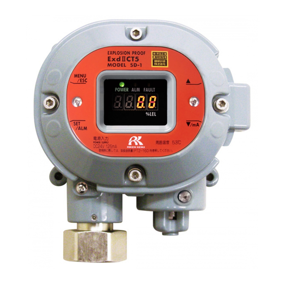
- Page 1 PT2E-1969 Smart transmitter/Gas Detector Head SD-1DRI Operating Manual (PT2E-196) (PT2-196)
- Page 2 Operating Precautions This detector is a gas detector that detects combustible gases in the air and triggers a gas alarm. The gas detector is a safety unit, not an analyzer or densitometer which performs quantitative/qualitative analysis/measurement for gases. Please fully understand the following points before using it, so that it can be used properly. This detector may be interfered by gases and vapors other than the gas to be detected.
-
Page 3: Table Of Contents
Operating Precautions <Contents> 1 Outline of the Product ......................1 1-1. Preface ..........................1 1-2. Purpose of use ........................1 1-3. Definition of DANGER, WARNING, CAUTION, and NOTE ..........1 1-4. Method of confirmation for Standards and Explosion proof specification ......2 2 Important Notices on Safety.................... -
Page 4: Outline Of The Product
Outline of the Product 1-1. Preface Thank you for choosing our smart transmitter/gas detector head SD-1DRI. Please check that the model number of the product you purchased is included in the specifications on this manual. This manual explains how to use the detector and its specifications. It contains information required for using the detector properly. -
Page 13: Product Components
3 Product Components 3-3. Block diagram 3-3. Block diagram <Electric Diagram> Power supply part POWER INPUT (24 VDC) Display (POWER) (ALARM) (FAULT) Alarm contact controller Seven-segment LED Controller (four-digit) (CPU) 1. Gas alarm contact (ALARM) Magnetic operation part 2. Fault contact (FAULT) (MENU/ESC) (▲) (▼) (SET) 3. -
Page 19: How To Use
4 How to Use 4-5. Installation procedure NOTE ・Our company-specified grease : BARRIERTA JFE 552 (manufactured by NOK KLUBER) If you can not prepare the specified grease, use one that meets the following requirements. 1. Material does not harden due to deterioration 2. -
Page 31: Operations And Functions
6 Operations and Functions 6-1. Gas alarm activation Operations and Functions 6-1. Gas alarm activation Gas alarm: Activated when the concentration of detected gas reaches or exceeds the alarm setpoint value. <<Auto-Reset>> NOTE The alarm setpoint is factory-set. Although the alarm delay time (standard: 2 seconds) works in the detector to prevent a false activation, it can be cancelled if not needed. -
Page 32: Fault Alarm Activation
6 Operations and Functions 6-2. Fault alarm activation <Response to Gas Alarm> A gas concentration value exceeds the alarm setpoint When a gas alarm is triggered, take actions in accordance with your management rules of gas alarm. Normally, take the following actions. ... -
Page 35: Maintenance
7 Maintenance 7-1. Maintenance intervals and items Maintenance This is an important instrument for the purpose of safety. To maintain the performance of the detector and improve the reliability of safety, perform a regular maintenance. 7-1. Maintenance intervals and items ... - Page 36 7 Maintenance 7-1. Maintenance intervals and items Main Services Power Supply Checks the power supply voltage. Check Verifies that the power lamp lights up. (Verifies that relevant points can be identified on the system.) (When a UPS (uninterruptible power system) is used, checks the operation with the UPS (uninterruptible power system).) Concentration Verifies that the concentration display value is zero by using the zero gas.
-
Page 48: Parts Replacement
※ After replacements having need of operation check by professional service engineers. To maintain the safety operation of the detector, please use our maintenance service. Request RIKEN KEIKI for it. NOTE The above replacement intervals are recommendation only. The intervals may change depending on the operating conditions. -
Page 50: Troubleshooting
9 Troubleshooting 9 Troubleshooting Troubleshooting The troubleshooting does not explain the causes of all the malfunctions which occur on the detector. This simply helps to find the causes of malfunctions which frequently occur. If the detector shows a symptom which is not explained in this manual, or still has malfunctions even though remedial actions are taken, please contact our overseas sales department or local representatives. - Page 51 9 Troubleshooting 9 Troubleshooting <Abnormalities of Readings> Symptoms Causes Actions Drifting of sensor Perform the zero adjustment. output Presence of Interference gas test including solvents are identified, interference gas and be treated properly. The reading rises A very small amount of the gas to be detected may be (drops) and it remains leaking (slow leak).
-
Page 52: Product Specifications
10 Product Specifications 10-1. List of specifications Product Specifications 10-1. List of specifications <ATEX/IECEx Specifications> Model SD-1DRI Detection principle Non-dispersive infrared absorption method Detection gas Combustible gas Concentration display LED(4digits・7segments) Detection range Depend on detection gas Resolution Depend on detection gas... -
Page 54: Detection Principle
10 Product Specifications 10-1. List of specifications <TIIS Specifications> Model SD-1DRI Detection principle Non-dispersive infrared absorption method Detection gas Combustible gas Concentration display LED(4digits・7segments) Detection range Depend on detection gas Resolution Depend on detection gas Detection method Suction method(pour into by external unit) Suction flow 1.0±0.1L/min... - Page 56 10 Product Specifications 10-1. List of specifications <Detectable gas list> Operating temperature Measuring Alarm Detectable gas Gas code TIIS ATEX/IECEx range point Specification Specification 0-100 %LEL 25.0 -20~53℃ -20~60℃ 1,2-Dichloroethane 0-100 %LEL 25.0 -10~53℃ -10~60℃ 1,3-Dioxolane 0-100 %LEL 25.0 -20~53℃ -20~60℃...
-
Page 58: Definition Of Terms
11 Definition of Terms Definition of Terms Non-dispersive This is a principle of the sensor installed in the detector head. infrared type See "10-2. Detection principle" for details. Output from the detector head fluctuates for a while after turning on the power. Initial clear This is a function to prevent triggering alarm during that time.


Need help?
Do you have a question about the SD-1DRI and is the answer not in the manual?
Questions and answers