Table of Contents
Advertisement
Quick Links
Advertisement
Table of Contents

Related Manuals for Lifelines Trackit M


Summary of Contents for Lifelines Trackit M
- Page 1 SYSTEM MANUAL is for Mobile DM00003 Rev D...
-
Page 2: Table Of Contents
Setting Up the Trackit M �����������������������������������������������������������������������������������������������������������������������������������������������18 Before You Begin ........................................18 7.2 Setting Up the Trackit M Main Unit ............................... 19 7.3 Setting Up the Video and IR Illuminator Assembly ........................21 7.4 Setting Up the Photic Stimulator ................................22 7.5 Setting Up an External Monitor ................................ - Page 3 9.4 Battery Management ......................................31 9.5 Systems Check ........................................31 9.6 Limited Use Items ........................................ 31 10 Troubleshooting ����������������������������������������������������������������������������������������������������������������������������������������������������������������32 Technical Specifications ����������������������������������������������������������������������������������������������������������������������������������������������35 11.1 Trackit M ............................................35 11.2 Amplifier .............................................36 11.3 Impedance Measurements ..................................36 11.4 Degree of Accuracy of On-Screen Measurements ........................37 11.5 Event Marker..........................................37 11.6 Photic Stimulator .........................................38...
- Page 4 Fig 3: Trackit M Connector Bay ..................................... 19 Fig 4: Trackit M Main Unit—Rear View ................................19 Fig 5: Trackit M Custom Headbox and Cable (left) and Standard 10/20 Headbox and Cable (right) ... 20 Fig 6: Event Marker Cable ......................................20 Fig 7: Video assembly ........................................
-
Page 5: Attention
Attention Attention No part of this document may be copied or reproduced in any form or by any means without prior written consent of Lifelines Neuro Company, LLC. 1�1 Customer Support Info In case of issues, requests, or for technical support, contact:... -
Page 6: Customer Responsibility
The owner of this system has the sole responsibility for any malfunction resulting from improper use or maintenance, or repair done by anyone other than a qualified Lifelines Neuro representative and for any malfunctions caused by any parts that have been damaged or modified by anyone other than a qualified Lifelines Neuro representative. -
Page 7: Safety
Safety Read this manual carefully before using the Trackit M for the first time to familiarize yourself with its operation. This manual is part of the product and must be available anytime. Use the device only for the intended purpose. Pay attention to all warnings, advice, and notes provided in this manual. - Page 8 Failure to comply may result in an explosion or fire. An approved Separation Device (isolation device) is required when connecting an external monitor to the Trackit M. The requirement for the Separation Device is defined in IEC 60601-1- 1 and in IEC 60601- 1, edition 3, clause 16.
- Page 9 Completely disconnect the device from the patient before using an electrical surgical unit. This Trackit M is not designed for use in or near MRI equipment. Failure to remove all sensor leads before performing an MRI can result in burn hazards to the patient. Using this equipment in or near an MRI can result in equipment malfunction due to magnetic noise from the MRI.
-
Page 10: Cautions For The Trackit M
Always disconnect all cables, turn off the device, and close the screen before transportation of the Trackit M to avoid injury and system damage. Also, to avoid system damage, only transport the system using approved packaging. -
Page 11: Explanation Of Symbols
SYSTEM MANUAL Explanation of Symbols Explanation of Symbols The following signs are used for marking the Trackit M and accessories: Symbol Meaning Symbol Meaning Alternating Current BF-type Applied Part Direct Current Class II Equipment Power / Stand-by Manufacturer name and address... -
Page 12: Getting To Know The Trackit
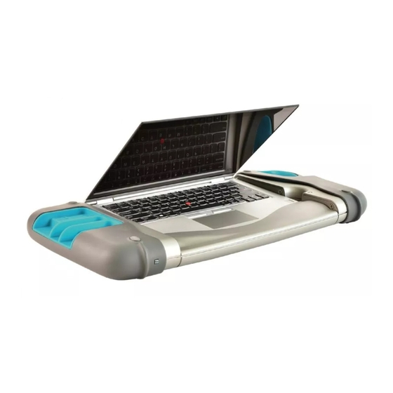
The Trackit M is intended to be used for such studies as electroencephalogram (EEG) and video EEG recording to aid in diagnosis. The Trackit M does not draw any diagnostic conclusions. -
Page 13: Parts List
SYSTEM MANUAL Getting to Know the Trackit M 6�2 Parts List 6�2�1 Standard Kit The following parts are provided as part of the Trackit M. Part Number Description PL00000 Trackit M DP00277 Wireless mouse DP00597 Trackit M EEG Power Cord (US) - Page 14 SYSTEM MANUAL Getting to Know the Trackit M 6�2�2 Patient Sensor Leads Part Number Description PL00008-32.00-34.75-37.50-G Midline Sensor Cable Gold, Long Length, Graduated PL00008-60.00-60.00-60.00-G Midline Sensor Cable, Long Length, Single Length PL00009-26.75-29.5-32.25-35.00-37.75-G Parasagittal Sensor Cable Gold - Long Length, Graduated PL00009-60.00-60.00-60.00-60.00-60.00-G...
-
Page 15: Understanding The Trackit M System Connections
SYSTEM MANUAL Understanding the Trackit M System Connections 6�3 Understanding the Trackit M System Connections Isolation (Optional) External Monitor Isolation Unit Power Power EEG Electrodes Sensors and HDMI Cable Sensor Leads Custom or Standard 10/20 EEG Headbox Patient Video Assembly... -
Page 16: Indicator Lights
SYSTEM MANUAL Understanding the Trackit M System Connections 6�4 Indicator Lights 6�4�1 Trackit M Indicator Light Color Status Green Powered On, Ready for use. No Light Powered Off 6�4�2 Photic Stimulator Light Color Status Green Powered On, Ready for use. -
Page 17: Understanding The Custom Eeg Headbox
SYSTEM MANUAL Understanding the Trackit M System Connections 6�5 Understanding the Custom EEG Headbox Fig 2: 10/20 Sensor Positions on Head DM00003 Rev D... - Page 18 6.5 Understanding the Custom EEG Headbox The Trackit M has two options for the Headbox cable (the Custom EEG Headbox and the Standard 10/20 EEG Headbox). The Custom EEG Headbox utilizes the Headlines Electrode System. Each sensor lead in the Headlines system is color- coordinated based on its location on the head, as shown on previous page.
- Page 19 See "Connecting the Sensor Leads" for more. Sensors and sensor leads are important components of the EEG system. All sensors and sensor leads should comply with Trackit M requirements. Lifelines Neuro recommends using Lifelines Neuro branded sensors in order to achieve optimum results.
-
Page 20: Understanding The Standard 10/20 Eeg Headbox
An "active ground" electrode that uses the Reference electrode to eliminate noise on the body, NEUTRAL) and brings the Trackit M to a neutral potential with respect to the body. Can be placed on either the forehead (Fpz) or the left or right mastoid. Is not a protective earth ground connection, and is protectively isolated from earth ground. -
Page 21: Understanding The Rendr Acquisition Software
6�7 Understanding the Rendr Acquisition Software The Rendr Acquisition Software manages the Trackit M hardware, collects and processes data, displays and prints reports, stores data, and provides the user interface. The Rendr Acquisition Software includes the following features: y Data acquisition and graphing... -
Page 22: Setting Up The Trackit
Customer Support for replacement. Arrange the system components observing safety requirements specified in this manual. Do not open the Trackit M casings if they are connected to the power supply unit due to risk of electric shock. Only Lifelines Neuro personnel should service the unit. -
Page 23: Setting Up The Trackit M Main Unit
Fig 4: Trackit M Main Unit—Rear View To get started with the Trackit M, set up the Trackit M main unit and connect the EEG cable and event marker. To set up the Trackit M main unit, EEG cable, and event marker 1. -
Page 24: Fig 5: Trackit M Custom Headbox And Cable (Left) And Standard 10/20 Headbox And Cable (Right)
Setting Up the Trackit M Fig 5: Trackit M Custom Headbox and Cable (left) and Standard 10/20 Headbox and Cable (right) 5. Remove the EEG cable and Headbox from the case. Connect the magnetized connector to the EEG cable port on the Trackit M. -
Page 25: Setting Up The Video And Ir Illuminator Assembly
2. Remove the video assembly from the case. Slide it onto the tripod, then tighten the rail lock. 3. Use the USB 2.0A to Mini-B cable (DP00812) to connect the assembly to the USB port on the back of the Trackit M. -
Page 26: Setting Up The Photic Stimulator
Fig 10: Photic Stimulator—Ports 4. Remove the photic stimulator cable from the case. Connect the magnetized connector to the stimulator port on the Trackit M, and plug the other end into the back of the photic stimulator. DM00003 Rev D... -
Page 27: Fig 11: Photic Stimulator Cable
SYSTEM MANUAL Setting Up the Trackit M 5. Plug in the power cord to the back of the photic stimulator, then plug the other end into an electrical outlet. Fig 11: Photic Stimulator Cable The Photic Stimulator is classified as a Group 2 instrument under ISO 15004-2. In the event of an electrical failure that turns the Photic Stimulator on at full brightness and at continuous wave stimulation (i.e., the photic stimulator turns on and remains on for more than 16 seconds), the light... -
Page 28: Setting Up An External Monitor
If in doubt, contact qualified medical technician or your local representative. An approved Separation Device (isolation device) is required when connecting an external monitor to the Trackit M. The requirement for the Separation Device is defined in IEC 60601-1- 1 and in IEC 60601- 1, edition 3, clause 16. -
Page 29: Operating The Trackit
Operating the Trackit M 8�1 Windows Login In order to use Trackit M, you must log into Windows through one of the following methods y Local User Account y Domain Account on Windows Server 2003 Active Directory or later 8�2... -
Page 30: Connecting The Sensor Leads Using The Custom Eeg Headbox
SYSTEM MANUAL Maintenance and Care 8�4 Connecting the sensor leads using the Custom EEG Headbox� To connect the sensors and sensor leads 1� Using D Clip snap in leads Connect the Ag-AgCl cup sensors to the sensor leads for all EEG channels. A snap should be heard when the cup is fully seated. -
Page 31: Connecting The Sensor Leads To The Standard 10/20 Eeg Headbox
SYSTEM MANUAL Maintenance and Care 8�5 Connecting the sensor leads to the Standard 10/20 EEG Headbox To Connect Single Electrodes 1. Using standard DIN 42-802 sensor leads: For all typical single electrode sensor leads (including snap-in, fixed cup, alligator clip, etc.), a single connector is provided for each lead on the Standard 10/20 EEG Headbox. 2. -
Page 32: Calibration Waveform Settings
Accessing Help At any time, click to access the Trackit M User Manual. Users experiencing an issue that cannot be solved may contact a Lifelines Neuro representative using the contact information provided in the front of this manual. DM00003 Rev D... -
Page 33: Maintenance And Care
9�1�5 Storage and Transport Stow the Trackit M in the Trackit M carrying case when not in use. Never transport the system unless properly stowed in the carrying case. If the device must be moved, it is recommended that the operator first disconnect all cables, install the dust cover, power down the device, and close the screen. -
Page 34: Cleaning Instructions
Avoid placing cable magnetic connectors near metal particles or parts. If any debris is found to be on cable connectors or the connector area of Trackit M, it must be removed or the cables may not connect properly. It is advised to wipe the area with a lint free cloth, and to clean the area thoroughly using compressed air. -
Page 35: Battery Management
9�5 Systems Check The Trackit M automatically performs a functional systems check when the device is powered on. If there is a system fault detected, the user will be notified in the Rendr Acquisition Software. 9�6 Limited Use Items Do not use limited life parts, like sensor leads, for longer than the specified number of uses or it may result in degraded performance due to regular wear and tear of the electrode cup plating. -
Page 36: 10 Troubleshooting
Technical Specifications 10 Troubleshooting To troubleshoot common issues with the Trackit M, follow the steps below. If the problem cannot be solved, contact a Lifelines Neuro representative using the contact information provided in the front of this manual. Problem Solutions... - Page 37 Note: If an internet connection exists, a syncing icon will appear in the lower right hand portion of the Graph screen. If an internet connection exists and the Trackit M is recording data, the icon will be glowing. If an internet connection is not available, the sync icon will be greyed out, which means the recorded data will be stored locally on the device.
- Page 38 Solutions Photic stimulator is not flashing Make sure the peripheral cable is properly and securely attached to the Trackit M. Make sure the peripheral cable is plugged into the photic stimulator. Make sure the power cable is plugged into the photic stimulator.
-
Page 39: 11 Technical Specifications
SYSTEM MANUAL Technical Specifications 11 Technical Specifications 11�1 Trackit M Category Specification Computer Manufacturer Lenovo ® Computer Model ThinkPad™ Yoga Family Screen Size (Touch Capable) 13.3” Maximum Screen Resolution 1920 x 1080 pixels Battery Capacity 51 Wh Processor 8th Generation Intel Core™... -
Page 40: Amplifier
SYSTEM MANUAL Technical Specifications Category Specification Atmospheric Pressure (Storage & Transport) 69.7kPa (3,048 m/10,000 feet) to 106 kPa (sea level 0 m / 0ft) 11�2 Amplifier Category Specification Number of Channels y Total 32 (Custom EEG Headbox) 31 (Standard 10/20 EEG Headbox) y EEG Channels y Differential Channels 3 (Custom EEG Headbox) -
Page 41: Degree Of Accuracy Of On-Screen Measurements
SYSTEM MANUAL Technical Description 11�4 Degree of Accuracy of On-Screen Measurements 11�4�1 Visual Degree of Accuracy Visual measurements are measurements taken using the on-screen legend in software. The accuracy of these measurements is a function of screen size, screen resolution, and user adjustable software settings like sensitivity and time-base. -
Page 42: Photic Stimulator
SYSTEM MANUAL Technical Description 11�6 Photic Stimulator Category Specification Power Requirements y Voltage 12 Vdc y Current Recommended Distance from Patient 20 cm Stimulation Light Intensity y LVL 1 Setting (Nominal) 3,000 lux y LVL 10 Setting (Nominal) 10,000 lux Stimulation Frequency y Minimum 1 Hz... -
Page 43: Video Assembly
SYSTEM MANUAL Technical Description 11�7 Video Assembly Category Specification Camera Manufacturer V.I.O Camera Model Stream Resolution (Max) 1280 x 720 pixels Framerate (Nominal) 24 frames/second Illumination (Minimum) 20 lux Power Requirements y Voltage 12 VDC y Current Weight 1.8 lbs IR Sensitivity 850 nm Optional PTZ camera specs... -
Page 44: 12 Technical Description
12�1 Sensing Channels The Trackit M is a 32-channel electroencephalographic system comprised of 29 EEG sensors and three differential sensing channels. The 29 EEG sensors are organized into 6 groups of signals. Five of the groups correspond to rostral to caudal lines within the standard 10/20 system (Left Temporal, Left Parasagittal, Midline, Right Parasagittal, and Right Temporal). -
Page 45: Common Mode Noise Rejection
12�7 Filtering The Trackit M utilizes a minimal amount of hardware filtering to allow the maximum amount of flexibility for a given application. Hardware filtering consists of an RFI filter to eliminate high frequency RF noise, a Low Frequency (High Pass) Filter to eliminate very low frequency DC components, and an anti-aliasing filter at the Analog to Digital Converters. -
Page 46: Fig 14: Low Frequency Filter
SYSTEM MANUAL Technical Description y High frequency filter y Notch filter The characteristics of each filter are shown below. Fig 14: Low Frequency Filter DM00003 Rev D... -
Page 47: Fig 15: High Frequency Filter
SYSTEM MANUAL Technical Description Fig 15: High Frequency Filter Fig 16: Notch Frequency Filter DM00003 Rev D... -
Page 48: Montages
SYSTEM MANUAL Technical Description 12�8 Montages The Trackit M measures each sensor with respect to the Reference electrode. The software then calculates all montages from the original referential montage. 12�8�1 Default Montages Bio- Average Circum- Ipsilateral Ear Linked Ear Longitudinal... -
Page 49: Guidance And Manufacturer's Declaration
Guidance and manufacturer's declaration - Electromagnetic Emissions The Trackit M is intended for use in the electromagnetic environment specified below. The customer or the user of the Trackit M should assure that it is used in such an environment. Emissions test... - Page 50 NOTE 1 UT is the a.c. mains voltage prior to application of the test level. NOTE 2 Essential perfomance for the Trackit M includes the ability to perform without any non-recoverable fault related to data and video acquisition, photic stimulation, impedance measurement, internal test signal injection, or battery charging, as well as all basic safety requirements per the applicable specifications.
- Page 51 RF transmitters, and electromagnetic site survey should be considered. If the measureed field strength in the location in which the Trackit M is used exceeds the applicable RF compliance level above, the Trackit M should be observed to verify normal operation. If abnormal performance is observed, additional measures may be necessary, such as re-orienting or relocating the Trackit M.
- Page 52 The Trackit M is intended for use in an electromagnetic environment in which radiated FR disturbances are controlled. The customer or the user of the Trackit M can help prevent electromagnetic interference by maintaining a minimum distance between portable and mobile RF communications equipment (transmitters) and the Trackit M as recommended below, according to the maximum output power of the communications equipment.
- Page 53 Trackit M is a trademark of Lifelines Neuro Company. Ambu is a trademark of Ambu, A/S. Lenovo and ThinkPad are trademarks of Lenovo Corporation. Intel and Intel Core are trademarks of Intel Corporation. All other product names and trademarks are the property of their respective owners ©...
Need help?
Do you have a question about the Trackit M and is the answer not in the manual?
Questions and answers