Table of Contents
Advertisement
Quick Links
Advertisement
Table of Contents

Related Manuals for HIKVISION DS-K3Y501SX Series


Summary of Contents for HIKVISION DS-K3Y501SX Series
- Page 1 DS-K3Y501SX Series Flap Barrier Quick Start Guide...
- Page 2 WITHOUT LIMITATION, MERCHANTABILITY, SATISFACTORY QUALITY, OR FITNESS FOR A PARTICULAR PURPOSE. THE USE OF THE PRODUCT BY YOU IS AT YOUR OWN RISK. IN NO EVENT WILL HIKVISION BE LIABLE TO YOU FOR ANY SPECIAL, CONSEQUENTIAL, INCIDENTAL, OR INDIRECT DAMAGES,...
- Page 3 During the use of device, personal data will be collected, stored and processed. To protect data, the development of Hikvision devices incorporates privacy by design principles. For example, for device with facial recognition features, biometrics data is stored in your device with encryption method;...
- Page 4 DS-K3Y501SX Series Flap Barrier Quick Start Guide Regulatory Information FCC Information Please take attention that changes or modification not expressly approved by the party responsible for compliance could void the user’s authority to operate the equipment. FCC compliance: This equipment has been tested and found to comply with the limits for a Class B digital device, pursuant to part 15 of the FCC Rules.
- Page 5 DS-K3Y501SX Series Flap Barrier Quick Start Guide under the EMC Directive 2014/30/EU, RE Directive 2014/53/EU,the RoHS Directive 2011/65/EU 2012/19/EU (WEEE directive): Products marked with this symbol cannot be disposed of as unsorted municipal waste in the European Union. For proper recycling, return this product to your local supplier upon the purchase of equivalent new equipment, or dispose of it at designated collection points.
- Page 6 DS-K3Y501SX Series Flap Barrier Quick Start Guide Safety Instruction These instructions are intended to ensure that user can use the product correctly to avoid danger or property loss. The precaution measure is divided into Dangers and Cautions: Dangers: Neglecting any of the warnings may cause serious injury or death.
- Page 7 DS-K3Y501SX Series Flap Barrier Quick Start Guide • If smoke, odors or noise rise from the device, turn off the power at once and unplug the power cable, and then please contact the service center. • Do not ingest battery, Chemical Burn Hazard.
- Page 8 DS-K3Y501SX Series Flap Barrier Quick Start Guide • Please use a soft and dry cloth when clean inside and outside surfaces of the device cover, do not use alkaline detergents. • Please keep all wrappers after unpack them for future use. In case of any failure occurred, you need to return the device to the factory with the original wrapper.
- Page 9 DS-K3Y501SX Series Flap Barrier Quick Start Guide Available Models Product Name Model Description Flap Barrier DS-K3Y501SX-L1 Left Pedestal 1 DS-K3Y501SX-L2 Left Pedestal 2 DS-K3Y501SX-M1 Middle Pedestal 1 DS-K3Y501SX-M2 Middle Pedestal 2 DS-K3Y501SX-R Right Pedestal You can follow the picture below to select pedestals: Scan the QR code to get User Manual of Flap Barrier.
-
Page 10: Table Of Contents
DS-K3Y501SX Series Flap Barrier Quick Start Guide Contents Chapter 1 Overview ........................1 1.1 Introduction ........................... 1 1.2 Main Features ........................1 Chapter 2 System Wiring ......................3 Chapter 3 Installation ......................... 6 3.1 Disassemble Pedestals ......................6 3.2 Install Pedestals ........................6 Chapter 4 General Wiring ...................... - Page 11 DS-K3Y501SX Series Flap Barrier Quick Start Guide 5.4 Switch Relay Output Mode (NO/NC) ..................27 5.4.1 Barrier Control Relay Output Mode ................27 5.4.2 Alarm Relay Output Mode (NO/NC) ................28 Chapter 6 Activation ......................... 29 6.1 Activate via SADP ......................... 29 6.2 Activate Device via Client Software ..................
-
Page 12: Chapter 1 Overview
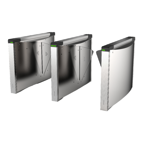
DS-K3Y501SX Series Flap Barrier Quick Start Guide Chapter 1 Overview 1.1 Introduction Figure 1-1 Appearance The flap barrier designed to detect unauthorized entrance or exit. By adopting the flap barrier integratedly with the access control system, person should authenticate to pass through the lane via presenting IC or ID card, scanning QR code, etc. - Page 13 DS-K3Y501SX Series Flap Barrier Quick Start Guide • Fire alarm passing When the fire alarm is triggered, the barrier will be open automatically for emergency evacuation • Valid passing duration settings System will cancel the passing permission if a person does not pass through the lane within the valid passing duration •...
-
Page 14: Chapter 2 System Wiring
DS-K3Y501SX Series Flap Barrier Quick Start Guide Chapter 2 System Wiring The preparation before installation and general wiring. Steps 1. Draw a central line on the installation surface of the left or right pedestal. 2. Draw other parallel lines for installing the other pedestals. - Page 15 DS-K3Y501SX Series Flap Barrier Quick Start Guide Figure 2-2 System Wiring Diagram (General Wiring) Note • The supplied interconnecting cable length is 5.5 m. • The suggested inner diameter of the low voltage conduit is larger than 30 mm. • If you want to bury both of the AC power cord and the low voltage cable at the entrance, the two cables should be in separated conduits to avoid interference.
- Page 16 DS-K3Y501SX Series Flap Barrier Quick Start Guide Figure 2-3 Wire Face Recognition Terminal Note • The left pedestal and the middle pedestal should bury interconnecting cables for connecting the face recognition terminal. • The face recognition terminal installed on the left pedestal will gain power from the sub switch, which should connect to high voltage.
-
Page 17: Chapter 3 Installation
DS-K3Y501SX Series Flap Barrier Quick Start Guide Chapter 3 Installation 3.1 Disassemble Pedestals Before installation, you should use the key to open the pedestals. View the pictures below to find the lock holes. Figure 3-1 Lock Holes 3.2 Install Pedestals... - Page 18 DS-K3Y501SX Series Flap Barrier Quick Start Guide Figure 3-2 Dimension 1. Prepare for the installation tools, check the components, and prepare for the installation base. 2. Drill holes on the ground according to the installation holes on the pedestals and insert the expansion sleeves.
- Page 19 DS-K3Y501SX Series Flap Barrier Quick Start Guide Figure 3-3 Entrance Mark on Pedestal Note Make sure the installation holes on the pedestals and the base are aligned with each other. 5. Secure the pedestals with expansion bolts. Note • Do not immerse the pedestal in the water. In special circumstances, the immersed height should be no more than 150 mm.
-
Page 20: Chapter 4 General Wiring
DS-K3Y501SX Series Flap Barrier Quick Start Guide Chapter 4 General Wiring 4.1 Components Introduction By default, basic components of the turnstile are connected well. The pedestals can communicate by wiring the interconnecting cables. And the turnstile supports wiring the AC electric supply for the whole system's power supply. -
Page 21: Wiring Electric Supply
DS-K3Y501SX Series Flap Barrier Quick Start Guide Figure 4-2 Components 2 Note • For details about wiring arrangement, refers to the actual device. • If the turnstile contains two lanes, standing at the entrance position, the IR modules on the left pedestal are the IR sending modules. -
Page 22: Wire Interconnecting Cable
DS-K3Y501SX Series Flap Barrier Quick Start Guide Note • The cable bare part should be no more than 8 mm. It is suggested that you can immerse the bare part into the liquid tin. If possible, wear an insulation cap at the end of the bare cable. -
Page 23: Face Recognition Terminal Power Supply Wiring
DS-K3Y501SX Series Flap Barrier Quick Start Guide Figure 4-4 Connect Interconnecting Cable 4.4 Face Recognition Terminal Power Supply Wiring You should wire the power supply terminal on the 12 V power supply component if you connect the turnstile to the face recognition terminal. -
Page 24: Terminal Description
DS-K3Y501SX Series Flap Barrier Quick Start Guide 4.5 Terminal Description The lane controller contains main lane controller and sub lane controller, which controls the IR beams, motor, and other components' work. 4.5.1 Main Control Board Terminal Description The main lane control board contains power supply interface, supercapacitor interface, brake... -
Page 25: Access Control Board Terminal Description
DS-K3Y501SX Series Flap Barrier Quick Start Guide Figure 4-7 Sub Control Board 4.5.3 Access Control Board Terminal Description Figure 4-8 Access Control Board Table 4-1 Access Control Board Terminal Description Access Control Board Terminal Description Power Output 1 +12 V... - Page 26 DS-K3Y501SX Series Flap Barrier Quick Start Guide Access Control Board Terminal Description Grounding Wiegand Card Indicator of Card Reader Control Output (Invalid Card Reader 2 Output) Indicator of Card Reader Control Output (Valid Card Output) Card Reader Buzzer Control Output...
- Page 27 DS-K3Y501SX Series Flap Barrier Quick Start Guide Access Control Board Terminal Description Grounding Event Alarm Input 1 Exit Button Door 2 Signal Input Grounding Door 1 Signal Input Door Lock (Relay) Door 1 Relay Output (Dry Contact) Door 2 Relay Output (Dry Contact)
-
Page 28: Access Control Board Serial Port Id Description
DS-K3Y501SX Series Flap Barrier Quick Start Guide • For any requirements, the door lock can control the door barrier status of the third party. D1 controls the barrier opening for entrance, while D2 controls the door opening for exit. For details, see Barrier Control Relay Output Mode . - Page 29 Use the jumper cap to switch the serial port communication mode with the lane controller. By default, the interface is wired and it is in RS-485 communication mode. If wiring other controllers (compatible with Hikvision communication protocol), use the jumper cap to switch between RS-485 and RS-232 communication mode.
-
Page 30: Rs-485 Wiring
DS-K3Y501SX Series Flap Barrier Quick Start Guide Figure 4-10 Interface and Corresponded UART No. 4.5.5 RS-485 Wiring... -
Page 31: Rs-232 Wiring
DS-K3Y501SX Series Flap Barrier Quick Start Guide Note • There are four RS-485 interfaces, which are for connecting ID card reader, IC card reader, QR code scanner, fingerprint and card reader, card recycler, fingerprint reader, and face recognition terminal. Take the wiring of RS-485 card reader as an example. -
Page 32: Wiegand Wiring
DS-K3Y501SX Series Flap Barrier Quick Start Guide 4.5.7 Wiegand Wiring Note Connect the OK/ERR/BZ if the access controller should control the LED and buzzer of the Wiegand card reader. 4.5.8 Barrier Control Wiring By default, the barrier has connected with the access control board. The lane control board can control the barrier status. - Page 33 DS-K3Y501SX Series Flap Barrier Quick Start Guide Entering Wiring Exiting Wiring...
-
Page 34: Alarm Output Wiring
DS-K3Y501SX Series Flap Barrier Quick Start Guide 4.5.9 Alarm Output Wiring Note For details about changing the relay output status via the jumper cap, see Alarm Relay Output Mode (NO/NC) . -
Page 35: Chapter 5 Device Settings
DS-K3Y501SX Series Flap Barrier Quick Start Guide Chapter 5 Device Settings After installation and wiring completed, the turnstile will learn the open and closed position automatically. After the learning, the turnstile is in the normal mode. You can also set the turnstile to test mode,... -
Page 36: Initialize Device
DS-K3Y501SX Series Flap Barrier Quick Start Guide 3. Power on the turnstile and it will enter the keyfob pairing mode. 4. Hold the Close button for more than 10 seconds. Or pair turnstile and keyfob in the client software, see Manage Keyfob User of the user manual for more details. -
Page 37: Switch To Rs-485/Rs-232 Mode
DS-K3Y501SX Series Flap Barrier Quick Start Guide Caution The initialization of the device will restore all the parameters to the default setting and all the device events are deleted. Note Make sure no persons are in the lane when powering on the device. -
Page 38: Switch Relay Output Mode (No/Nc)
DS-K3Y501SX Series Flap Barrier Quick Start Guide Figure 5-3 Jumper Cap Status of RS-232 Interface 5.4 Switch Relay Output Mode (NO/NC) 5.4.1 Barrier Control Relay Output Mode The pins of the barrier control relay on the access control board is as below:... -
Page 39: Alarm Relay Output Mode (No/Nc)
DS-K3Y501SX Series Flap Barrier Quick Start Guide The jumper cap's position of barrier closing for exit (NC) is as below: 5.4.2 Alarm Relay Output Mode (NO/NC) Alarm Relay Output Mode (NO): Alarm Relay Output Mode (NC):... -
Page 40: Chapter 6 Activation
• Get the SADP software from the supplied disk or the official website http:// www.hikvision.com/en/ , and install the SADP according to the prompts. • The device and the PC that runs the SADP tool should be within the same subnet. -
Page 41: Activate Device Via Client Software
DS-K3Y501SX Series Flap Barrier Quick Start Guide Status of the device becomes Active after successful activation. 5. Modify IP address of the device. 1) Select the device. 2) Change the device IP address to the same subnet as your computer by either modifying the IP address manually or checking Enable DHCP. - Page 42 DS-K3Y501SX Series Flap Barrier Quick Start Guide three kinds of following categories: upper case letters, lower case letters, numbers, and special characters) in order to increase the security of your product. And we recommend you change your password regularly, especially in the high security system, changing the password monthly or weekly can better protect your product.
-
Page 43: Appendix A. Tips For Scanning Fingerprint
DS-K3Y501SX Series Flap Barrier Quick Start Guide Appendix A. Tips for Scanning Fingerprint Recommended Finger Forefinger, middle finger or the third finger. Correct Scanning The figure displayed below is the correct way to scan your finger: You should press your finger on the scanner horizontally. The center of your scanned finger should align with the scanner center. - Page 44 DS-K3Y501SX Series Flap Barrier Quick Start Guide Others If your fingerprint is shallow, or it is hard to scan your fingerprint, we recommend you to use other authentication methods. If you have injuries on the scanned finger, the scanner may not recognize. You can change another...
-
Page 45: Appendix B. Dip Switch
DS-K3Y501SX Series Flap Barrier Quick Start Guide Appendix B. DIP Switch B.1 DIP Switch Description The DIP switch is on the main lane control board. No.1 to No 8 is from the low bit to the high bit. When the switch is towards ON, it means the switch is enabled, otherwise, the switch is off. If you set the DIP switch like the figure displayed below, its binary value is 00001100, and its decimal value is 12. - Page 46 DS-K3Y501SX Series Flap Barrier Quick Start Guide Device Mode Function Decimal Value Binary Value Keyfob Paring Enable Keyfob Mode Paring Mode Disable Keyfob Paring Mode 5 to 8 Passing Mode Controlled Bi- direction Controlled Entrance and Prohibit Exit Controlled Entrance and Free Exit Free Bi-...
-
Page 47: Appendix C. Event And Alarm Type
DS-K3Y501SX Series Flap Barrier Quick Start Guide Appendix C. Event and Alarm Type Event Alarm Type Tailgating Visual and Audible Reverse Passing Visual and Audible Force Accessing None Climb over Barrier Visual and Audible Overstay Visual and Audible Passing Timeout... -
Page 48: Appendix D. Table Of Audio Index Related Content
DS-K3Y501SX Series Flap Barrier Quick Start Guide Appendix D. Table of Audio Index Related Content Index Content Authenticated. Card No. does not exist. Card No. and fingerprint mismatch. Climbing over the barrier. Reverse passing. Passing timeout. Intrusion. Force accessing. Tailgating. -
Page 49: Appendix E. Error Code Description
DS-K3Y501SX Series Flap Barrier Quick Start Guide Appendix E. Error Code Description The swing barrier will display the error code on the seven-segment display if error occurred. Refer to the table below to find the description of each number. Error Reason... - Page 50 DS-K3Y501SX Series Flap Barrier Quick Start Guide Error Reason Code Error Reason Code The Third IR Beam on Lower IR Lower IR Board 8 Offline Board Triggered The Fourth IR Beam on Lower Lower IR Board 9 Offline IR Board Triggered...
-
Page 51: Appendix F. Communication Matrix And Device Command
Device Command Scan the following QR code to get the device common serial port commands. Note that the command list contains all commonly used serial ports commands for all Hikvision access control and video intercom devices. Figure F-2 Device Command... - Page 52 UD23009B...
Need help?
Do you have a question about the DS-K3Y501SX Series and is the answer not in the manual?
Questions and answers