Advertisement
Quick Links
Installation Instructions
L[G]E[W]-6-60[-X] Series
SW3-1010 - v2
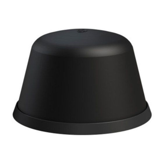
1. Introduction
The L[G]E[W]-6-60[-X] antenna series is a range of low profile antennas incorporating a wideband 4G/5G frequencies along with an optional active
GPS/GNSS/BEIDOU antenna with 26dB LNA gain and optional 2x2, 3x3 or 4x4 WiFi. The antenna range can be deployed with or without a conductive
ground plane.
Electrical Safety Note
This product contains an active GPS antenna (part number SR8-JG26NS). Rated voltage: 3-5VDC Rated current: 20mA maximum.
The supply to this device must be provided with overcurrent protection of 1A maximum.
2. Mounting Requirements and Selecting Location
This antenna range can be deployed with or without a conductive ground plane although the presence or absence of a ground plane will impact on
performance.
Ensure that there is adequate under panel clearance and that there is no double skin panel or cross brace present. Measure to check for central position if
applicable. For optimal performance the antenna should, if possible, be mounted at least 300mm (1ft) away from other conductive objects on the mounting
panel.
3. Prepare and Drill Hole
Mask panel area around hole position to protect paintwork and headliner.
Drill a pilot hole, and then increase to 19mm (3/4"), ensuring that drill/cutter bit does not contact headliner. Clean area
around the hole, carefully removing all swarf. Do not mount to a hole larger than 19mm diameter.
Hole
19
If mounting to a conductive ground plane remove paint and primer from under panel surface to ensure adequate earth
contact by washer and nut. Apply some petroleum jelly or paint around the hole to prevent corrosion.
4. Fitting the Antenna
Remove protective backing from underside of antenna, feed coaxial cable(s) through panel. Position the antenna over the hole and stick to panel by applying
firm downward pressure. Assemble nut from underside and tighten.
IMPORTANT: Do not exceed a torque of 5Nm (3.6ft/lbs) when tightening the mounting nut.
5. Routing and Terminating Coaxial Cable(s)
Connect extension coaxial cables to antenna and route to equipment, taking care to avoid fouling any moving vehicle component. The cables must not be
routed in front of any airbag device.
Advertisement

Related Manuals for Panorama Antennas L E 6-60 Series


Summary of Contents for Panorama Antennas L E 6-60 Series
- Page 1 Installation Instructions L[G]E[W]-6-60[-X] Series SW3-1010 - v2 1. Introduction The L[G]E[W]-6-60[-X] antenna series is a range of low profile antennas incorporating a wideband 4G/5G frequencies along with an optional active GPS/GNSS/BEIDOU antenna with 26dB LNA gain and optional 2x2, 3x3 or 4x4 WiFi. The antenna range can be deployed with or without a conductive ground plane.
- Page 2 6. Commission and test Check comms cables: ● Carry out VSWR check, VSWR should measure as per datasheet. Check GPS cable (if applicable): ● Check the GPS cable with DC to measure high resistance. ● Connect the GPS cable to the GPS receiver and check for satellite acquisition. 7.