Table of Contents
Advertisement
Quick Links
Advertisement
Table of Contents

Related Manuals for frako PQA 1101


Summary of Contents for frako PQA 1101
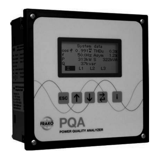
- Page 1 OPERATING MANUAL PQA 1101 Power Quality Analyzer Power system monitoring An instrument for the acquisition, analysis and monitoring of all key electrical data in low voltage 3-phase systems from 115 V to 690 V FRAKO Kondensatoren- und Anlagenbau GmbH www.frako.com...
-
Page 2: Table Of Contents
Display............27 Power Quality Analyzer 1101 – PQA | Operating Manual | FRAKO... - Page 3 Disposal ........... . 56 Notes ��������������������������������������������������������������������������������������������������������57 FRAKO | Operating Manual | Power Quality Analyzer 1101 – PQA...
-
Page 4: About This Manual
Throughout this operating manual the Power Quality Analyzer PQA will be referred to simply as the PQA. The most recent update of this manual can always be found on our website www.frako.com. Objective This operating manual has been prepared for persons who install, connect, commis- sion and operate the PQA. -
Page 5: Reference Documents
Example of a note Reference documents For further information relevant to this manual please refer to the following documents: – Modbus Specification – REST Application Note About this manual | 5 FRAKO | Operating Manual | Power Quality Analyzer 1101 – PQA... -
Page 6: Safety
The load ratings for the various connections must not be exceeded. – Do not open the PQA. – When the PQA is in operation, the USB port must not be touched. 6 | Safety Power Quality Analyzer 1101 – PQA | Operating Manual | FRAKO... -
Page 7: Management Information
Incorrect operation or failure to observe the safety instructions will invalidate all claims under the guarantee, and no liability is accepted for any injuries to persons or dam- ages to assets arising therefrom or occasioned thereby! Safety | 7 FRAKO | Operating Manual | Power Quality Analyzer 1101 – PQA... -
Page 8: Relevant Standards
Should repair work be necessary, the customer or user must contact the manufacturer of the PQA: FRAKO Kondensatoren und Anlagenbau GmbH, Tscheulinstrasse 21A, D-79331 Teningen, Germany, www.frako.com. 8 | Safety Power Quality Analyzer 1101 – PQA | Operating Manual | FRAKO... -
Page 9: Technical Data
10 A AC for 10 seconds Temperature Two PT100 RTDs, 4-wire or 2-wire inputs configuration, measurement range S0 pulse as per DIN 43864, common earth with FRAKO Starkstrombus Tariff switching (T) (Frakobus) Interfaces: Type Modbus 120 Ω terminating... - Page 10 USB for updates USB Micro A and Micro B ports (service interface) The output relays of the PQA 1101 with firmware version 1.0 cannot be used. 10 | Technical data Power Quality Analyzer 1101 – PQA | Operating Manual | FRAKO...
- Page 11 Flammability rating UL 94 V-0 according to casing manufacturer Casing design Impact resistance IK06 as per EN 61010-1:2011-07, 8.2.2 Service life At +25 °C ambient temperature 15 years Technical data | 11 FRAKO | Operating Manual | Power Quality Analyzer 1101 – PQA...
- Page 12 For this reason, the radio-frequency field test can only be carried out without amplitude modulation. 12 | Technical data Power Quality Analyzer 1101 – PQA | Operating Manual | FRAKO...
-
Page 13: Instrument Description
Its contact can give an alarm signal when variables move outside set limits. The PQA 1101 has been designed to integrate into the FRAKO Energy Management System, where it can exhibit its full potential. An integral bus interface enables con- nection to the FRAKO Starkstrombus or a Modbus RTU/TCP bus. -
Page 14: Password Protection
Once the 4th numeral has been confirmed, the menus with the corresponding security level are enabled for one hour. 14 | Instrument description Power Quality Analyzer 1101 – PQA | Operating Manual | FRAKO... -
Page 15: Installation
– The PQA must be mounted in an adequately ventilated area. Its rear and sidewalls must not be covered. Installation | 15 FRAKO | Operating Manual | Power Quality Analyzer 1101 – PQA... -
Page 16: Mounting The Instrument
For this an additional gasket (Article No. 20-50015) is available that seals the gap between the PQA front panel and the wall of the control cabinet. 16 | Installation Power Quality Analyzer 1101 – PQA | Operating Manual | FRAKO... -
Page 17: Electrical Installation
– When the PQA is being fitted and connected, the instrument and the electrical system must be isolated from the power supply. Installation | 17 FRAKO | Operating Manual | Power Quality Analyzer 1101 – PQA... -
Page 18: Completing The Electrical Installation
18 | Installation Power Quality Analyzer 1101 – PQA | Operating Manual | FRAKO... -
Page 19: Specifications For The Electrical Connections
PQA. This must be located in the vicinity of the instrument and must be able to isolate all cables connected to the AUX terminals of the PQA. This device must not disconnect the earthing conductor. Installation | 19 FRAKO | Operating Manual | Power Quality Analyzer 1101 – PQA... -
Page 20: Voltage Measurement
L1 and N must be used. The terminals L2 und L3 must then be commoned with the terminal N to prevent incorrect measurements being made. 20 | Installation Power Quality Analyzer 1101 – PQA | Operating Manual | FRAKO... -
Page 21: Current Measurement
Section 5.2.9, Connection diagrams. Attention must be paid to the load rating of the contact (see Section 3, Technical data). Installation | 21 FRAKO | Operating Manual | Power Quality Analyzer 1101 – PQA... -
Page 22: Connection Diagrams
φ φ 250 VAC~ 3A cos 250 VAC~ 3A cos Profilum- schaltung Profile Switching Alarm Alarm FRAKO Starkstrombus ϑ ϑ PT100 PT100 Power Bus Alarm 22 | Installation Power Quality Analyzer 1101 – PQA | Operating Manual | FRAKO... - Page 23 φ 250 VAC~ 3A cos 250VAC~3A cos 250 VAC~ 3 A cos Profilum- schaltung Profile Switching Alarm Alarm FRAKO ϑ ϑ Starkstrombus PT100 PT100 Power Bus Installation | 23 FRAKO | Operating Manual | Power Quality Analyzer 1101 – PQA...
-
Page 24: Commissioning
Initial start-up Select Select Confirm language Function Main menu language language and return to – dt – en – fr dt – en – fr parameter selection 24 | Installation Power Quality Analyzer 1101 – PQA | Operating Manual | FRAKO... - Page 25 In the event of power loss (intended or not) these data are not lost. When the power supply returns, the PQA starts up automatically and begins the data acquisition process after booting up. Installation | 25 FRAKO | Operating Manual | Power Quality Analyzer 1101 – PQA...
-
Page 26: Description Of The Menu
Main menu Display Configuration About PQA System System & PQ parameters Temperatures Alarms Alarms & Communi- Serial notifications cation System Temperatures time Service 26 | Description of the menu Power Quality Analyzer 1101 – PQA | Operating Manual | FRAKO... -
Page 27: Display
System Alarm data phase history Current Min/Max diagramm data V/I har- monics V harm. spectrum I harm. spectrum Work counter Frequency analysis Description of the menu | 27 FRAKO | Operating Manual | Power Quality Analyzer 1101 – PQA... -
Page 28: System & Pq
Each individual phase can then be selected at the lower edge of the screen. Navigate Back to – – between – Function System & PQ ∑/L1/L2/L3 28 | Description of the menu Power Quality Analyzer 1101 – PQA | Operating Manual | FRAKO... - Page 29 Momentary measured phase apparent power Momentary measured phase power factor Momentary measured phase active power (fundamental frequency) Momentary measured power factor (cos φ) of fundamental frequency Description of the menu | 29 FRAKO | Operating Manual | Power Quality Analyzer 1101 – PQA...
- Page 30 Display of the voltage and current harmonics as percent- ages together with the fundamental voltage and current. Navigate Navigate Change the Back to Function – System & PQ upwards downwards phase 30 | Description of the menu Power Quality Analyzer 1101 – PQA | Operating Manual | FRAKO...
- Page 31 50/60 Hz is defined as 100%. One graduation on the y-axis represents 5%. Change Change the harmonics Back to Zoom + Zoom - Function System & PQ phase 1 – 12/ 8 – 19 Description of the menu | 31 FRAKO | Operating Manual | Power Quality Analyzer 1101 – PQA...
- Page 32 Angle between V and I in degrees (fundamental) (EN 61000-3-12, EN 50160:2008) Frequency Frequency Select Function Info Status – +10 Hz -10 Hz phase 32 | Description of the menu Power Quality Analyzer 1101 – PQA | Operating Manual | FRAKO...
-
Page 33: Alarms & Notifications
(sorted by time). Selecting one of the lines shown and pressing the key causes the alarm condition to be displayed in plain language. Description of the menu | 33 FRAKO | Operating Manual | Power Quality Analyzer 1101 – PQA... - Page 34 • PT1 • PT2 Note Pressing the key shows the times elapsed since the minimum and maximum values displayed on the screen occurred. 34 | Description of the menu Power Quality Analyzer 1101 – PQA | Operating Manual | FRAKO...
-
Page 35: Configuration
Nominal Relay Factory frequency setting settings Reset CT ratio Low load Min/Max Reset PT ratio Alarm history Reset Work counter Service Description of the menu | 35 FRAKO | Operating Manual | Power Quality Analyzer 1101 – PQA... -
Page 36: System Parameters
Setting parameter Setting range Default 10 MW Low load limit P – 36 | Description of the menu Power Quality Analyzer 1101 – PQA | Operating Manual | FRAKO... - Page 37 – Transmission via communication channel The PQA has the communication options FRAKO Starkstrombus, Modbus RTU and Modbus TCP, enabling the alarm register to be read remotely for all existing alarms.
- Page 38 (see also Section 6.3.2, Alarms). Setting parameter Setting range Default value Alarm relay Display Asymmetry [Asym] 0 – 100% ON/OFF ON/OFF 38 | Description of the menu Power Quality Analyzer 1101 – PQA | Operating Manual | FRAKO...
- Page 39 Setting parameter Setting range Default value Alarm relay Display Current min [A] 0 – 30 kA ON/OFF ON/OFF Description of the menu | 39 FRAKO | Operating Manual | Power Quality Analyzer 1101 – PQA...
- Page 40 As soon as a THDi reading rises above the set limit, an alarm is initiated. Setting parameter Setting range Default value Alarm relay Display 5 – 500 [%] 100% ON/OFF ON/OFF I max L1=L2=L3 40 | Description of the menu Power Quality Analyzer 1101 – PQA | Operating Manual | FRAKO...
- Page 41 6.3.2.11 V harmonics Main menu > Configuration > Alarms > Alarms > V harmonics Alarm limit 0% to 100% (in increments of 0.01%) Description of the menu | 41 FRAKO | Operating Manual | Power Quality Analyzer 1101 – PQA...
- Page 42 Default value Alarm relay Display 0 – 100 [%] 100% h2 max – . – ON/OFF ON/OFF 0 – 100 [%] 100% h19 max Default according to EN 61000-2-4 42 | Description of the menu Power Quality Analyzer 1101 – PQA | Operating Manual | FRAKO...
- Page 43 ON/OFF ON/OFF PT100-1 alarm max. -50 – +200 °C -50 °C ON/OFF ON/OFF PT100-2 alarm min. -50 – +200 °C 60 °C ON/OFF ON/OFF PT100-2 alarm max. Description of the menu | 43 FRAKO | Operating Manual | Power Quality Analyzer 1101 – PQA...
-
Page 44: Communication
The PQA is accessible via the Modbus TCP/IP protocol and port 502 at the set IP address. The data that can be retrieved are listed in the FRAKO Modbus Specification. 44 | Description of the menu... - Page 45 PT100 Power Bus Alarm The PQA bus address can be set either at the instrument itself or via the FRAKO Energy Management System. Description of the menu | 45 FRAKO | Operating Manual | Power Quality Analyzer 1101 – PQA...
- Page 46 Data bits 5 to 8 Stop bits 1 or 2 Parity even, odd or none Note Further details are described in the Modbus Specification. 46 | Description of the menu Power Quality Analyzer 1101 – PQA | Operating Manual | FRAKO...
-
Page 47: Service
Reset the work counter readings for Tariffs T1 and T2 totalized up until the present time. 6.3.4.6 Service Main menu > Configuration > Service > Service Optional service functions. Temp-I/O Update Software update mode for Temp I/O Description of the menu | 47 FRAKO | Operating Manual | Power Quality Analyzer 1101 – PQA... -
Page 48: About Pqa
Display 1.5% / 5 / 5 – – 110% Voltage Alarm relay 1.5 / 30 / 5 Display 1.5 / 30 / 5 48 | Description of the menu Power Quality Analyzer 1101 – PQA | Operating Manual | FRAKO... - Page 49 1.5 / 60 / 60 – / – / – Sensitivity Voltage sag Alarm relay – / – / – Display – / – / – Description of the menu | 49 FRAKO | Operating Manual | Power Quality Analyzer 1101 – PQA...
-
Page 50: Service Interface
Note This interface is solely for the use of trained FRAKO Service personnel. For further information concerning firmware updates please contact FRAKO Service by telephone at +49 7641 453 544 or by e-mail at service@frako.de. -
Page 51: General Operation
– All voltages applied to the instrument must never exceed the limits specified in the technical data. – The ambient temperatures must always be within the range specified in the technical data. General operation | 51 FRAKO | Operating Manual | Power Quality Analyzer 1101 – PQA... -
Page 52: Cleaning And Maintenance
The PQA may only be cleaned with a dry cloth. Do not use aggressive or abrasive cleaning agents or solvents. Maintenance The PQA does not contain any components that need maintenance. 52 | Cleaning and maintenance Power Quality Analyzer 1101 – PQA | Operating Manual | FRAKO... -
Page 53: Troubleshooting
Auto to the appropriate is connected and a system frequency (50 Hz current is flowing. or 60 Hz). V harm. > set Voltage harmonics in limit system too high Troubleshooting | 53 FRAKO | Operating Manual | Power Quality Analyzer 1101 – PQA... - Page 54 – resistance in the power the instrument restarts supply circuit? repeatedly. Note Additional error notifications are described in the PQA Application Note. 54 | Troubleshooting Power Quality Analyzer 1101 – PQA | Operating Manual | FRAKO...
-
Page 55: Decommissioning And Removal, Storage And Disposal
3. Individually isolate and insulate all disconnected cables and take measures to pre- vent their inadvertent contact with live components or electrically conducting parts. Decommissioning and removal, storage and disposal | 55 FRAKO | Operating Manual | Power Quality Analyzer 1101 – PQA... -
Page 56: Pqa Removal
Germany, or the company’s local representatives. Alternatively, the instru- ments can be given to a firm specializing in the recycling of electronic equipment. 56 | Decommissioning and removal, storage and disposal Power Quality Analyzer 1101 – PQA | Operating Manual | FRAKO... -
Page 57: Notes
Notes Notes | 57 FRAKO | Operating Manual | Power Quality Analyzer 1101 – PQA... - Page 58 58 | Notes Power Quality Analyzer 1101 – PQA | Operating Manual | FRAKO...
- Page 59 Notes | 59 FRAKO | Operating Manual | Power Quality Analyzer 1101 – PQA...
- Page 60 Reactive power control relays Power factor correction systems Modules EMS components Measuring instruments and network analyzers Power quality EMS ISO 50001 FRAKO Kondensatoren- und Anlagenbau GmbH Tscheulinstraße 21a D-79331 Teningen Tel: +49 7641 453-0 Fax: +49 7641 453-535 sales@frako.de www.frako.com...
Need help?
Do you have a question about the PQA 1101 and is the answer not in the manual?
Questions and answers