Table of Contents

Related Manuals for frako EM-PQ 2500


Summary of Contents for frako EM-PQ 2500
- Page 1 Power Quality Analyzer EM-PQ 2500 Operating Manual FRAKO Kondensatoren- und Anlagenbau GmbH • Tscheulinstraße 21a • 79331 Teningen • Germany Tel. +49 7641 453-0 • Fax +49 7641 453-535 • http://www.frako.de • E-Mail: info@frako.de...
- Page 2 Index of Contents General Configuration Language Goods-in Check Communication Description Measurement Intended Use Transients Features Events Measurement Method Display EM-PQ VIS software System settings Assembly Password Place of Installation Delete minimum and maximum values Installation extradata Delete power meters Front Board Cutout Extensions Ethernet Connection Initialization...
-
Page 3: Protected Trademarks
All trademarks and the resulting rights belong to the respective owners of the rights. Disclaimer FRAKO Kondensatoren- und Anlagenbau GmbH does not accept any liability for errors or deficits in this handbook and is not obliged to keep the contents of this handbook updated. -
Page 4: Meaning Of Symbols
Safety information Meaning of Symbols The following pictograms are used in this hand- book: Gefährliche Spannung! Protective ground connection. Danger of death or risk of major injury. Disconnect the system and device be- fore beginning any work. Inductive. The voltage lags the current Caution! Capacitive. -
Page 5: Application Information
Safety Information Application Information Specialists are persons who, due to their rele- Please read this operating manual and all other vant training and experience, are capable of re- publications that have to be consulted to work cognizing risks and avoiding possible hazards with this product (particularly for installation, that can be caused when operating or servicing operation or maintenance). -
Page 6: Goods-In Check
Goods-in Check Goods-in Check Correct and safe operation of this device is subject to appropriate transportation, correct warehousing, installation and assembly as well as careful operation and maintenance. If it can be assumed that safe operation without any danger is no longer possible, the device must be taken out of operation immediately and se- cured against unintentional initialization. -
Page 7: Scope Of Supply
Goods-in Check Scope of Supply Number Name EM-PQ2500 Operating manual CD with the following contents: - Configuration and visualization software „EM-PQ VIS“ - Functional descriptions, EM-PQ VIS, EM-PQ2500 .. - GSD file „U5080C2C.GSD“ for Profibus DP V0 Screw clamp, pluggable, 2-pole (auxiliary power). Screw clamp, pluggable, 5-pole (voltage measurement 1-4). -
Page 8: Intended Use
Description Description Intended Use The EM-PQ2500 is intended for measurements in the building installation, on distributors, pow- er switches and bus bars. Measurement voltages and measurement cur- rents must come from the same network. The EM-PQ2500 is suitable for installation in switch boards with a fixed, weather-protected extradata. - Page 9 Description Features • Front board installation, 144x144mm, • Working temperature range -10°C .. +55°C, • Colour graphic display 320x240, 256 colours, 6 keys, • 8 digital inputs, 5 digital outputs, • 16Bit A/transformer, data memory 256MByte Flash, SDRAM 32Mbyte, • Continuous scanning of voltage and current measurement inputs with 20kHz, • Frequency range of fundamental oscillation 40Hz ..
-
Page 10: Measurement Method
Description Measurement Method The EM-PQ2500 measures without any gaps and calculates all effective values over a 200ms Interval. The EM-PQ2500 measures the real effective va- lue (TRMS) of the voltages and currents applied to the measurement inputs. Operating Concept You can program the EM-PQ2500 in several ways and call up measurement values. - Page 11 Description EM-PQ VIS configuration and visualization software Interface Converter The EM-PQ2500 can be programmed and read- out with the EM-PQ VIS configuration and vi- RS232 sualization software included in the scope of PQ2500 supply. A PC must be connected using a serial RS485 interface (RS485/Ethernet) to the EM-PQ2500.
-
Page 12: Place Of Installation
Assembly Assembly Place of Installation The EM-PQ2500 is suitable for installation in fixed, weather protected switch boards. Con- ducting switch boards have to be grounded. Installation extradata In order to achieve sufficient ventilation, the EM- PQ2500 has to be installed vertically. The clea- EM-PQ2500 rance has to be at least 50mm at the top and bottom and 20mm at the side. -
Page 13: Ethernet Connection
Assembly Ethernet Connection The EM-PQ2500's Ethernet connection is loca- ted on the underside of the housing. Depending on the bending radius of the Ether- net cable and plug type, you must provide a connection area beneath the EM-PQ2500. Ethernet Connection 50 mm The connection area beneath the EM-PQ2500 Patch Cable... -
Page 14: Installation
Installation Installation Separator Connection point for Protective Wire Connection protective wire Use a ring cable lug for connecting the protecti- Fuse Protective wire ve wire to the EM-PQ2500. Supply Voltage A supply voltage is required to operate the EM- PQ2500. The type and level of the necessary supply voltage is noted on the label. - Page 15 Installation Warning! The inputs for the supply voltage are dangerous to touch! Warning! Please pay attention to the details on the supply voltage provided on the EM-PQ2500 label. - An isolator or circuit breaker must be provided for the voltage supply in buil- ding installation.
- Page 16 Installation Voltage Measurement Three-phase 3 conductor systems The EM-PQ2500 is only suitable for use in IT Three-phase 4 conductor systems networks with restrictions, because the measu- The EM-PQ2500 can be used in three-phase rement voltage is measured against the housing 4 conductor systems (TN, TT network) with a potential and the input impedance of the device grounded neutral wire.
- Page 17 Installation Nominal Voltages Lists of the networks and their nominal network voltages in which the EM-PQ2500 can be used. Ungrounded three-phase 3 conductor systems. Three-phase 4 conductor systems with grounded neutral wire. 115V 120V 66V / 115V 127V 120V / 208V 200V 127V / 220V 220V...
-
Page 18: Voltage Measurement Inputs
Installation Voltage Measurement Inputs N PE The EM-PQ2500 has 4 voltage measurement inputs (V1, V2, V3, V4). Overvoltage The voltage measurement inputs are suitable for measurements in networks in which overvolta- ges in the overvoltage category 600V CATIII can occur. Frequency The EM-PQ2500 requires the rated frequency for measuring and calculating measurement va-... - Page 19 Installation The following has to be considered when con- Warning! necting the voltage measurement: Voltages that exceed the authorized • A suitable separator is to be provided in order network nominal voltages must be to disconnect the EM-PQ2500 from the cur- connected using a voltage converter.
- Page 20 Installation Connection diagrams, voltage measurement...
- Page 21 Installation Connection diagrams, current measurement...
-
Page 22: Current Measurement
Installation Current measurement N PE The EM-PQ2500 is designed for connecting current converters with secondary currents of ../1A and ../5A. Only alternating currents, and no direct currents, can be measured. Each current measurement input can be loaded with 120A for 1 second. Warning! The current measurement inputs are dangerous to touch. -
Page 23: Current Direction
Installation Current Direction The current direction can corrected on the de- vice or individually using the available serial in- terfaces for each phase. In the case of incorrect connection, subsequent reconnection of the current converter is not ne- cessary. Current converter connections! Open current converters! The secondary connections of the cur- Extreme contact danger due to voltage... -
Page 24: Total Current Measurement
1000/5A. The total mea- surement is carried out with a 5+5/5A total cur- rent converter. The EM-PQ2500 must then be set as follows: EM-PQ 2500 Primary current: 1000A + 1000A = 2000A Secondary current: Illu. Example, current measurement using a total... -
Page 25: Direct Measurement
4 wire systems with mains voltage till • 127V/220V (300V CAT III) according UL • 277V/480V (300V CAT III) EM-PQ 2500 and three phase 3 wire systems with mains volt- age till • 277V (300V CAT III) according UL •... - Page 26 Installation RS485 The RS485 interface is designed as a 9-pole DSUB socket on the EM-PQ2500. On this interface, the EM-PQ2500 supports the following selection of protocols: • Modbus RTU • Profibus DP V0 Slave For connection, we recommend a 9-pole Pro- fibus plug, e.g.
- Page 27 (switch to ON). In switch extradata ON, clamps 2A and 2B are switched off for the continuing bus line. EM-PQ 2500 Illu. Profibus plug with terminating resistors.
- Page 28 Installation Shields A twisted, shielded cable is foreseen for con- Cable nections using the RS485 interface. • Ground the shields of all cables leading to the Strain relief cabinet at the cabinet entry point. • Connect the shield extensively and with Cable shielding braid.
- Page 29 Installation Bus structure • All devices are connected in a bus structure • We recommend to install the master device (line). at the end of the segment. • In one segment, up to 32 participants can be • In case that the master device with termina- switched together.
- Page 30 Installation Ethernet The network settings for the Ethernet are speci- fied by the network administrator and set accor- dingly on the EM-PQ2500. If the network settings are not known, the patch cable may not be plugged into the EM-PQ2500. Ethernet connection Patch cable Warning! Incorrect nework settings can cause...
- Page 31 Installation DHCP EM-PQ2500 EM-PQ2500 Server Patch cable Patch cable (twisted) Illu. Connection example; direct connection bet- Switch ween the EM-PQ2500 and PC using a twisted patch cable. Illu. Connection example; EM-PQ2500 and PC are automatically allocated the IP address from a DHCP server.
-
Page 32: Digital Outputs
Installation Digital outputs The EM-PQ2500 has 5 digital outputs. These outputs are separated galvanically from the ana- lysis electronics using optocouplers. The digital outputs have a common reference. • The digital outputs can switch AC and DC loads. • The digital outputs arenotshort-circuit proof. • Connected lines that are longer than 30m must be laid with shields. - Page 33 Installation External auxiliary power EM-PQ2500 Digital outputs 1-5 Digital Outputs 1-5 Digital Output 5 Digital Output 4 Digital Output 3 Digital Output 2 Digital Output 1 Illu. Connection of two relays to digital outputs 4 and 5.
-
Page 34: Digital Inputs
Installation Digital Inputs The EM-PQ2500 has 8 digital inputs. The digital inputs are divided into two groups, each with 4 inputs. Each group has a common reference. External auxiliary power EM-PQ2500 Digital Inputs 1-4 Digital Inputs 1-4 3.9V Digital Input 1 3.9V Digital Input 2... - Page 35 Installation S0 impulse input You can connect an S0 impulse generator in ac- cordance with DIN EN62053-31 to each digital input. You require an external auxiliary voltage with an output voltage in the range of 20 .. 28V DC and External a resistor with 1.5kOhm.
-
Page 36: Operation
Operation Operation The EM-PQ2500 is operated using six function keys. The six keys are allocated different functions depending on the context: • Selection of measurement value displays. • Navigation within the menu. • Processing the device settings. Display titles Measurement values Function key labeling Function keys... -
Page 37: Measurement Value Displays
Operation Measurement value displays Main values You can use keys 2 and 5 to browse between the main values of the measurement value dis- plays. Display Display Display Display Pointer dia- "Home“ Configuration Voltages L-N gram Main values Auxiliary values You can use keys 3 and 4 to browse between Display the auxiliary values of a measurement value dis-... -
Page 38: "Home" Measurement Value Display
Operation "Home“ measurement value display Once the network returns, the EM-PQ2500 starts with the "Home“ measurement value dis- play. This measurement value display contains the device names and an overview of important measurement values. The device name consists of the device type and serial number upon de- livery. -
Page 39: Select Measurement Value Display
Operation Select measurement value display You want to change to a measurement value display with main values. • Use the function keys 2 and 5 to browse bet- ween the measurement value displays of the main values. • With function key 1 (Home), you always ac- cess the first measurement value display. -
Page 40: Call Up Additional Information
Operation Call up additional information • Browse with keys 2 to 5 to the required mea- surement value display. • Activate the measurement value selection with key 6 (selection). • Select the required measurement value with keys 2 to 5. • The background colour for the measurement value changes from grey to green. -
Page 41: Delete Min/Max Values Individually
Operation Delete min/max values individually • Use keys 2 to 5 to browse to the required measurement value display. • Activate the measurement value selection with key 6 (selection). • Select the required minimum and maximum value with keys 2 to 5. • The background colour for the measurement value changes from grey to green. -
Page 42: List Of Transients
Operation List of transients Recognized transients are listed in the transi- ents list. • The transients list consists of 2 pages. • Transients 1 to 8 are listed on page 1 and 9 to 16 on page 2. Display transients • Go to the transients list with key 6 "selec- tion". -
Page 43: List Of Events
Operation List of events Recognized events are listed in the events list. • The events list consists of 2 pages. • Events 1 to 8 are listed on page 1 and events 9 to 18 on page 2. Display incident • Go to the events list with key 6 "Selection". - Page 44 Configuration Configuration The supply voltage must be connected for con- figuration of the EM-PQ2500. Apply supply voltage • The level of supply voltage for the EM- PQ2500 can be taken from the label. • After applying the supply voltage, a startup screen appears on the display.
-
Page 45: Configuration Menu
Configuration Configuration menu Once the network returns, the "Home" measure- ment value display is found on the start page. • Browse to the menu configuration with key 1. If you are in a measurement value display for main values, you use • key 1 - "Home“... -
Page 46: Configuration - Communication
Configuration - communication Communication The EM-PQ2500 has an Ethernet and a RS485 interface. Ethernet (TCP/IP) Select the type of address allocation for the Ethernet interface here. DHCP mode • Off- IP address, Netmask and Gateway are specified by the user and set directly on the EM-PQ2500. - Page 47 Configuration - communication RS485 You can specify the protocol, the device address and the Baud rate for operating the RS485 inter- face. Protocol Selection options: • Modbus Slave • Modbus Master/Gateway • Profibus DP V0 Factory pre-setting: Modbus Master/Gateway Device address Setting range: 0 - 255 Factory pre-setting:...
-
Page 48: Configuration - Measurement
Configuration - measurement Measurement Configure here: • The measurement converters for the current and voltage measurement. • The record of transients. • The recording of events. • The rated frequency. - Page 49 Configuration - measurement Rated frequency For measuring and calculating the meaurement values, the EM-PQ2500 requires the Rated fre- quency of a.c. systems. The EM-PQ2500 is suitable for measurements in networks with a rated frequency in the range of 40Hz to 70Hz. The rated frequency can be specified by the user or automatically detected by the device.
- Page 50 Configuration - measurement Voltage converter You can allocate the main meaurement and the auxiliary measurement voltage converter rela- tions. You select the setting 400 V / 400 V for measu- rements without a voltage converter. Setting range: Primary 1 .. 999,999 V Secondary 1 ..
- Page 51 Configuration - measurement Connection diagram for voltage measurement For the voltage measurement, you can select between the following connection diagrams: 3p4w - 3 phase 4 conductor 3p4wu - 3 phase 4 conductor 3p3w - 3 phase 4 conductor For networks without a neutral conductor under symmetric load.
- Page 52 Configuration - measurement Current converter You can allocate both the main measurement and auxiliary measurement current converter relations. Select setting 5/5A for direct measurement of currents. Setting range: Primary 1 .. 999,999 A Secondary 1 .. 5 A Factory pre-setting: Primary Secondary Nominal current...
- Page 53 Configuration - measurement Connection diagram for current measurement You can select between the following connec- tion diagrams for current measurement: 3p4w - 3 phase 4 conductor, 3 current conv. 3p5w - 3 phase 4 conductor, 4 current conv. The fourth current transformer can be used for measuring the neutral conductor e.g.
- Page 54 Configuration - measurement Transients Transient voltages are rapid, impulsive transi- ent oscillation processes in electrical networks. Transient voltages are not predictable with res- pect to time and last for a limited period. Transient voltages are caused by the effects of lighting, due to switching operations or the trig- gering of fuses.
- Page 55 Configuration - measurement Mode (absolute) If a scanning value exceeds the set limit value, a transient is recognized. • Off- Transient monitoring is switched off • Automatic- Factory pre-setting. The limit va- lue is automatically calculated and is 110% of the current 200 ms effective value.
- Page 56 Configuration - measurement Events Events are limit value violations of effective cur- rent and voltage values. The EM-PQ2500 compares the limit values with the full wave rms values (20ms/16.7ms) of cur- rent and voltage. • You can specify limit values for each current input and each voltage input.
- Page 57 Configuration - measurement Voltage Drop A drop in voltage is set in % of the nominal vol- tage. Overvoltage The overvoltage is set in % of the nominal vol- tage. Current Overcurrent The rapid increase of current is set in % of the nominal current.
-
Page 58: Configuration - Display
Configuration - display Display Brightness The brightness level of the background illumi- nation can be adjusted. The brightness level set here is used during operation of the EM- PQ2500. Setting range: 0 .. 100% Factory pre-setting: (0% = dark, 100% = very bright) Standby This refers to the time before the brightness changes to "standby brightness". - Page 59 Configuration - display Transition time You can set the time between automatic transiti- on to the next measurement value display. Setting range: 0 .. 255 seconds Factory pre-setting: 2 seconds The service life of the background il- lumination extends if the brightness of the background illumination is kept lower.
-
Page 60: Configuration - System
Configuration - system System settings Display of system settings specific to the de- vice. Firmware version Device serial number Fixed device MAC address Set IP address Set Gateway address Date and time Set password Illu. Example for the display of system settings. Reset settings You cannot configure the date and time directly on the device. - Page 61 Configuration - system Password The user can block access to the configuration with a password. Changing the configuration di- rectly on the device is then only possible after entering the password. The password consists of a 6 digit combination of numbers. Setting range: 1-999999 = with password 000000 = without password...
- Page 62 Configuration - system Delete minimum and maximum values You can delete all minimum and maximum valu- es in the EM-PQ2500 simultaneously. How to delete the individual minimum and maxi- mum values is described in the chapter "indivi- dually deleting min. and max. values". Delete all minimum and maximum values.
-
Page 63: Delete Power Meters
Configuration - system Delete power meters You can delete all power meters in the EM- PQ2500 at the same time. A selection of certain power meters is not pos- sible. • Select with key 3 "yes“ • Confirm with key 6. • The message "executed"... - Page 64 Configuration - system Delivered condition All settings such as the configuration and recor- ded data are reset to the factory pre-settings or deleted. Entered release codes are not deleted. • Select with key 3 "yes“ • Confirm with key 6. • The message "executed"...
- Page 65 Configuration - system Colors Selection of colors for the presentation of cur- rent and voltage in the graphic presentations.
- Page 66 Configuration - system Extensions Under "Extensions“ you can subsequently re- lease charged functions and show the status of Jasic programs.
- Page 67 Configuration - system Release The EM-PQ2500 contains chargeable functions that can be subsequently released. List of release functions: • BACnet • EMAX You receive the release code from the manufac- turer. The manufacturer needs the device serial number and the name of function to be released. In order to release the function, you enter the 6 digit release code in the respective line.
- Page 68 Configuration - system Jasic status Up to 7 specific customer Jasic programs (1-7) and one recording can run in the EM-PQ2500. The Jasic programs can adopt the following sta- tuses: • Stopped • Running You cannot change the status of Jasic programs on the device.
- Page 69 Configuration - system...
-
Page 70: Applying The Supply Voltage
Initialization Initialization Applying the supply voltage • The level of supply voltage for the EM- PQ2500 can be taken from the label. • After applying the supply voltage, a startup screen appears on the display. Around ten seconds later, the EM-PQ2500 changes to the first measurement value display. -
Page 71: Apply Measurement Voltage
Initialization Apply measurement voltage Rotary field direction • Voltage measurements in networks with Check the direction of the voltage rotary field nominal voltages above 500VAC against on the measurement value display of the EM- ground must be connected using a voltage PQ2500. -
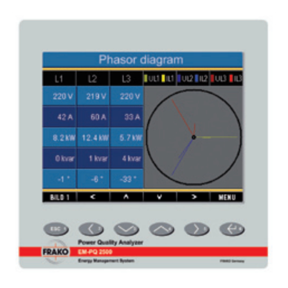
Page 72: Applying Measurement Current
Initialization Applying measurement current The EM-PQ2500 is designed for the connection of ../1A and ../5A current converters. Only AC currents, and not DC currents, can be measured using the current measurement in- puts. Short-circuit all current converter outputs ex- cept one. Compare the currents displayed by the EM-PQ2500 with the applied current. - Page 73 Initialization Pointer diagram, examplel 1 Primarily ohmic load. Voltage current only have a minor difference in the pha- • The current measurement input is allocated to the right voltage measurement input. Pointer diagram, example 2 Primarily ohmic load. Voltage current have a difference of approximately 180°...
-
Page 74: Checking The Power Measurement
Initialization Checking the power measurement Short-circuit all current converter outputs ex- cept one and check the displayed power out- puts. The EM-PQ2500 may only display one power output in the phase with the current converter input that is not short-circuited. If this does not apply, please check the connection of the mea- surement voltage and measurement current. -
Page 75: Checking Communication
Initialization Checking communication The EM-PQ2500 counts all received (RX), all sent (TX) and all faulty data packages. In the ideal case, the number of errors shown in the error column is zero. Reset You can delete the counters for the data pa- ckages with key 6. - Page 76 Profibus Profibus profile Device master file A Profibus profile contains data to be exchanged The device master file, abbreviated with GSD between a device and an SPS. Four Profibus file, describes the Profibus characteristics of profiles are pre-configured in the factory. the EM-PQ2500.
- Page 77 Profibus Example Collect measurement values using Profibus You must transfer at least one Profibus pro- file with EM-PQ VIS and transfer it to the EM- PQ2500. A Jasic program is not necessary. Illu. Block switch diagram for data exchange between PLC and EM-PQ2500.
- Page 78 Profibus Profibus profile number 0 Profibus profile number 1 Byte Value Scaling Byte- Values- Scaling Index Value type format Index Value type format Voltage L1-N Float Voltage L1-N float Voltage L2-N Float Voltage L2-N float Voltage L3-N float Voltage L3-N Float Voltage L4-N float...
- Page 79 Profibus Profibus profile number 2 Profibus profile number 3 Byte- Values- Scaling Byte- Values- Scaling Index Value type Format Index Value type Format Effective consumption total L1-L3 Float Effective power L1 Float Drawn eff. consum. total L1-L3 Float Effective power L2 Float Supplied eff.
-
Page 80: Service And Maintenance
Service and Maintenance Service and Maintenance The device is subjected to different safety tests Disposal before delivery and marked with a seal. If a de- The EM-PQ2500 can be recycled as electronic vice is opened, the safety tests have to be re- scrap in accordance with the legal regulations. - Page 82 Service and Maintenance Procedure in case of errors Remedy Possible error Cause Replace fuse. None Display. External fuse for the supply vol- tage has triggered. Connect measurement voltage. None Current dis- The measurement voltage is not play. connected. Connect measurement current. The measurement current is not connected.
- Page 83 Service and Maintenance Possible errors Cause Remedy Effective power is The programmed current Read and program the current conver- too high or low. converter transfer ratio is ter transfer ratio on the current conver- wrong. ter. The current path is allocated Check the connection and correct if to the wrong voltage path.
-
Page 84: Technical Data
Technical data Technical data General Net weight : 1080g Device dimensions : approx. l=144mm, w=144mm, h=75mm Battery : Type VARTA CR1/2AA, 3 V, Li-Mn Service life of background illumination : 40000h (50% of initial brightness) Transport and storage The following details apply to devices transported or stored in the original packaging. Free fall : 1m Temperature... - Page 85 Technical data Environmental conditions in operation The EM-PQ2500 is intended for use in a weather-protected, fixed extradata. The EM-PQ2500 must be connected to the protective wire connection! Protection class I accor- ding to IEC 60536 (VDE 0106, part 1). Calculation temperature range : K55 (-10°C ..
- Page 86 Technical data Supply voltage Installation overvoltage category : II Safeguarding of supply voltage Circuit breaker : 6A typ C ( approved by UL/IEC) 230V Nominal range : 95V .. 240V (45-65Hz) or DC 80V .. 340V Working range : +-10% of nominal range Power consumption : max.
- Page 87 Technical data Inputs and outputs 8 digital inputs Maximum counting frequency : 20Hz Reaction time (Jasic program) : 200ms Input signal applied : 18V .. 28V DC (typical 4mA) Input signal not applied : 0 .. 5V DC, current lower than 0.5mA 5 digital outputs, semi-conductor relay, not short-circuit proof.
- Page 88 Technical data Measurement inputs Voltage measurement The voltage measuring inputs are suitable for the following grids of power supply: Three-phase 4 conductor systems L-N/L-L : 417V/720V (+10%) Three-phase 3 conductor systems L-L : 600V (+10%) The voltage measuring inputs regarding safety and reliability reasons are dimensioned as follows: Overvoltage category : 600V CAT III Measurement surge voltage...
- Page 89 Technical data Current measurement Rated current : 5A Resolution : 0,1mA Measuring range : 0,001 .. 8,5Arms Crest factor : 2,4 Overvoltage category : 300V CAT III Measurement surge voltage : 4kV Power consumption : ca. 0.2 VA, (Ri=5mOhm) Overload for 1 second : 120A (sinusoidal) Scanning frequency : 20kHz...
- Page 90 Technical data Specifications (Measurement using current converters ../5A) Network quality parameters Function Symbol Accuracy class Measur. range Display range Frequency 0.05 (IEC61557-12) 40 .. 70 Hz 40 Hz .. 70 Hz Phase current 0.2 (IEC61557-12) 0.001 .. 8.5 Arms 0 A .. 9999 kA Neutral cond.
- Page 91 Technical data Function parameters Function Symbol Accuracy class Measurem. range Display range Total effective power (IEC61557-12) 0 .. 15.3kW 0 W .. 9999 GW Total reactive power QA, Qv (IEC61557-12) 0 .. 15.3 kvar 0 varh .. 9999 Gvar Total apparent power SA, Sv (IEC61557-12) 0 ..
- Page 92 Technical data Serial interfaces RS485 : plug, SUB D 9-pole Protocol, Modbus RTU : Modbus RTU/Slave, Modbus RTU/Master Transfer rate : 9.6kbps, 19.2kbps, 38.4kbps, 57.6kbps, 115.2kbps, 921.6kbps Protocol, Profibus : Profibus DP/V0 according to EN 50170 Transfer rate : 9.6kBaud to 12MBaud Ethernet 10/100Base-TX Connection : RJ-45...
- Page 93 Appendix Declaration of Conformity The EM-PQ2500 fulfils the following protection requirements: Directive 2004/108/EG in connection with DIN EN61326-1 (2006-10) as well as directive 2006/95/EG in connection with EN 61010-1 (2002-08) Safety requirements Safety requirements for electrical instrumentation, control and laboratory equipment : EN 61010-1 08:2002, IEC 61010-1:2001 Noise immunity DIN EN 61326-1:2006-10...
-
Page 94: Dimensioned Drawings
Technical data Dimensioned drawings +0,8 +0,8 Cutout size x 138 Reverse side Patch cable... - Page 95 Technical data Side view View from below...
-
Page 96: Configuration Overview
Configuration overview Other main values Display Display Display Communication Home Voltage L-N State Measurement values Other main values overview) (config) Configuration Language, Communication, Measurement, System Display, Colors, Extensions Communication Measurement Display System Colors Extensions Ethernet Transformer Information U, I Activation Feldbus Transients Password... - Page 97 Configuration overview Main values Device name Voltage Current Sum Real Overview L1..L4 Power L1..L4 (Real Power Measurement L1..L3) values (config) Configuration Voltage Current Reactive Power (Sum Real Power L1..L3) Apparent Power (Sum Real Power L1..L3)
-
Page 98: Measurement Value Displays Overview
Measurement value displays overview Main values Active Energy Active Energy Voltage Voltage Overview Monthly values Harmonics L1 Curve L1 (L2, L3, L4) (L2, L3, L4) Bar diagram (Tariff 1, Tariff 2) Reactive Energy Reactive Energy Current Current Overview Monthly values Harmonics L1 Curve (L2, L3, L4) - Page 99 Measurement value displays overview Main values Transients Events Phasor Communication 1..8 1..8 Diagram State (9..16) (9..16)
- Page 100 Connection example EM-PQ 2500...
Need help?
Do you have a question about the EM-PQ 2500 and is the answer not in the manual?
Questions and answers