Table of Contents
Advertisement
Quick Links
Advertisement
Table of Contents

Related Manuals for VWR International 1570


Summary of Contents for VWR International 1570
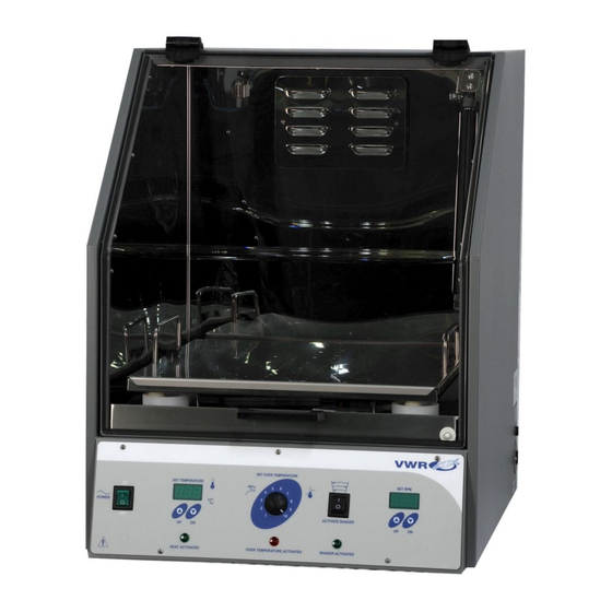
- Page 1 INCUBATOR MODEL: 1570 ORBITAL SHAKING INCUBATOR 09/11 4861479 INSTALLATION AND OPERATIONAL MANUAL Sheldon Manufacturing Inc. P.O. Box 627 Cornelius, Oregon 97113 EMAIL: tech@Shellab.com INTERNET: http://www.Shellab.com/~Shellab 1-800-322-4897 (503) 640-3000 FAX (503) 640-1366...
-
Page 2: Table Of Contents
TABLE OF CONTENTS SECTION 1.0 RECEIVING AND INSPECTION SECTION 2.0 GRAPHIC SYMBOLS SECTION 3.0 INSTALLATION SECTION 4.0 CONTROL OVERVIEW SECTION 5.0 OPERATION SECTION 6.0 MAINTENANCE SECTION 7.0 TROUBLESHOOTING SECTION 8.0 PARTS LIST SECTION 9.0 SPECIFICATIONS WIRE DIAGRAM This incubator shaker is for professional use where the preparation or testing of materials is done at approximately atmospheric pressure and no flammable, volatile or combustible materials are being heated. -
Page 3: Receiving And Inspection
Section RECEIVING AND INSPECTION Your satisfaction and safety require a complete understanding of this unit. Read the instructions thoroughly and be sure all operators are given adequate training before attempting to put the unit in service. NOTE: This equipment must be used only for its intended application;... -
Page 4: Graphic Symbols
Section GRAPHIC SYMBOLS Graphic symbols on the incubator have the following meanings. Indicates that you should consult your manual for further description or discussion of a control or user item. Indicates “Temperature”. Indicates “Over Temperature Safety”. C Indicates “Degrees Centigrade”. Indicates “AC Power”. -
Page 5: Installation
Section INSTALLATION Local city, county or other ordinances may govern the use of this equipment. If you have any questions about local requirements, please contact the appropriate local agency. Installation may be performed by the end user. Under normal circumstances this unit is intended for use indoors, at room temperatures and with a supply voltage that does not vary by more than 10%. -
Page 6: Control Overview
Section CONTROL PANEL OVERVIEW Power Switch: The main power I/O (on/off) switch controls all power to the incubator and must be in the I/ON position before any systems are operational. Main Temperature Control: Marked SET TEMPERATURE, the Main Temperature Control consists of the digital display and UP/DOWN arrow pads for inputting set point temperatures and calibration. -
Page 7: Operation
Section OPERATION Check power supply against unit serial plate. They must match. Plug service cord into the grounded electrical outlet. Push the power switch to the On position, and turn the Safety Thermostat to its maximum position, clockwise. Installing Platform: The platform is positioned by enclosing all corners of the shaking mechanism within the lips of the platform. -
Page 8: Maintenance
Section MAINTENANCE Note: Prior to any maintenance or service on this unit, disconnect the power cord from the power supply. Cleaning: Clean with mild soap and water solution, rinse with distilled water and wipe dry with a soft cloth. Disinfecting: Disinfect incubator interior... - Page 9 Table 1 shows counterbalance starting locations. For example, 5 kg of sample load being shaken with ½ inch stroke will require four counterweights attached to the counterbalance platform as shown in Figure 1. Loads should be properly counterbalanced before continuous operation. Unbalanced loading may damage mechanical and electrical operating systems.
-
Page 10: Troubleshooting
Section TROUBLESHOOTING TEMPERATURE Temperature too high-display and reference thermometer don‘t match 1/ Controller set too high-see section 5.5. 2/ Controller failed on – call Customer Service. 3/ Wiring error – call Customer Service. Display reads "HI" Probe is unplugged, is broken or wire to sensor is broken – trace wire from display to probe;... - Page 11 Indicated chamber temperature unstable 1/ ±0.1 may be normal. 2/ Is ambient radically changing – either door opening or room airflow from heaters or air conditioning ? – stabilize ambient conditions. 3/ Calibration sensitivity – call Customer Service. 4/ OTP set too low – be sure that its setting is more than 5 degrees over desired set point.
- Page 12 1/ Check wall power source. 2/ Check fuse/circuit breaker on unit or in wall. 3/ Check all wiring connections, especially around the on/off switch. Contamination in chamber 1/ See cleaning procedure in operator‘s manual. 2/ Develop and follow standard operating procedure for specific application, cleaning technique and maintenance schedule.
-
Page 13: Parts List
Section PARTS LIST Part Description 115V 220V 220V CE Adjustable feet 2700506 Control, Motherboard 1750716 Display, RPM 1750731 Display, Temperature 1750677 Door, Dual Shock 6400534 Door, Gas Shock Dual, ea 7600511 Door, Lift Spring Single 7600519 Door, Single Spring 6400555 Drive Belt, Oscillator 0500512 Element... -
Page 14: Specifications
Section UNIT SPECIFICATIONS MODEL 1570 TEMPERATURE Range Ambient +5C to 60C Ambient +9F to 158F Uniformity +.5C Sensitivity 0.1C Alarms Visual Safety Lamps CAPACITY Volume 113L 4.0 CF DIMENSIONS Interior (WxDxH) 44cmx44cmx44cm 17" x 17" x 17" Exterior (WxDxH) 74cmx69cmx104cm 29"... -
Page 15: Wire Diagram
10000J Motor 9570894 - 230V 4880514 CHAMBER FAN 4880527 — 120V 4880528 — 240V BALLAST X1000124 4660501 — 120V FLUORESCENT LIGHT IS NOT AVAILABLE ON THE 1570 4660506 — 240V F15-T8 4650528 PART OF 110-240V REFRIGERATION REFRIGERATION UNIT UNIT 120V... - Page 16 SHELDON MANUFACTURING, INC. LIMITED WARRANTY Sheldon Manufacturing, Inc., (“Manufacturer”) warrants for the original user of this product in the U.S.A. only that this pro duct (parts only if outside of the U.S.A.) will be free from defects in material and workmanship for a period of two years from the date of delivery of this product to the original user (the “Warranty Period”).
- Page 17 Edmonton, Alberta San Diego, CA Lake Charles, LA S. Plainfield, NJ San Dimas, CA Or Call Direct for Specialized Service Locations: VWR International Switzerland VWR Furniture Division 3000 Hadley Rd Ruchligstrasse # 20 P.O. Box 3405 S. Plainfield, NJ 07080 P.O.
Need help?
Do you have a question about the 1570 and is the answer not in the manual?
Questions and answers