Table of Contents
Advertisement
Advertisement
Table of Contents

Subscribe to Our Youtube Channel
Related Manuals for VWR International INCU-Line 68R


Summary of Contents for VWR International INCU-Line 68R
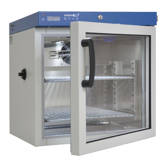
- Page 1 VWR Cooled Incubators INCU-Line 68R: 390-0728 INCU-Line 150R: 390-0729 INCU-Line 250R: 390-0731 Before using the equipment, please read carefully this instruction manual! Version 3.6...
- Page 2 Instruction Manual INCU-Line Cooled Legal Adress of Manufacturer: Country of Origin: Poland Page 2 / 32...
- Page 3 Instruction Manual INCU-Line Cooled Page 3 / 32...
- Page 4 Instruction Manual INCU-Line Cooled Page 4 / 32...
-
Page 5: Table Of Contents
Instruction Manual INCU-Line Cooled Contents IMPORTANT INFORMATION FOR THE USER ............. 7 PACKAGE CONTENTS ....................7 BEFORE THE FIRST USE ..................... 8 Installation of shelf ....................9 Remarks on the type of samples ................9 Remarks on the placement of samples ..............10 DEVICE DESCRIPTION .................... - Page 6 Instruction Manual INCU-Line Cooled 14.1 Housing cleaning ....................26 14.2 Interior cleaning ..................... 27 15 RESUMING OPERATION AFTER A LONGER PERIOD OF TIME ......27 16 TROUBLESHOOTING ....................28 16.1 REPLACEMANT OF FUSE ..................29 17 PRODUCT IDENTIFICATION LABEL ................29 18 WARRANTY CONDITIONS ..................
-
Page 7: Important Information For The User
PACKAGE CONTENTS INCU-Line devices are delivered with the following equipment: INCU-Line 68R, 2 wire shelves with set of slides – 2 pcs. each, keys to the lock (2pcs.), Manufacturer test certificate at 37 C, Multilingual instruction manual and Basic Control Software (on CD) for download data from internal memory INCU-Line 150R, 2 wire shelves with set of slides –... -
Page 8: Before The First Use
45°, then after placing it, please wait at least 3 hours before connecting the unit to the mains. The place of installation of the unit should meet the following conditions: • Ambient temperature +10°C...+28°C, for INCU-Line 68R (with glass door) +10°C...+25°C, • Low relative humidity of the ambient air to 60% •... -
Page 9: Installation Of Shelf
Instruction Manual INCU-Line Cooled 3.1 Installation of shelf Perform the following steps to adjust shelf height: 1) Install the shelf holder at the selected height by inserting it into proper slots on the wall. 2) Insert the shelf into the holder on one side. 3) Slide the second shelf holder onto the other side of the shelf. -
Page 10: Remarks On The Placement Of Samples
Instruction Manual INCU-Line Cooled If water gathers, use a dry cloth to wipe the bottom of the chamber. Do not use any cardboard boxes, sponges and other hygroscopic materials for storing the samples since they may increase the relative humidity in the chamber. 3.3 Remarks on the placement of samples To provide proper air circulation and stable conditions in which the samples are stored in the chamber, it is necessary to keep the following rules:... -
Page 11: Device Description
Instruction Manual INCU-Line Cooled 4 DEVICE DESCRIPTION (1) RS-232C and USB socket (2) Electronic controller with LCD display (3) Chamber fan (4) Access port (30mm) (5) Shelf (6) Key lock (7) Main switch (8) Internal electrical socket (9) Internal lighting LED (10) Temperature sensor (11) Height adjustable feets (12) Mains socket (for power cable) -
Page 12: Control Panel
Internal lighting LED Internal lighting is switched on automatically when the outside door is open. For INCU-Line 68R the internal light can be switched on even when the glass door is closed. Press down the enter button and hold it for about 2 sec to switch on the light. -
Page 13: Programming Possibilities
Instruction Manual INCU-Line Cooled 4.2 Programming possibilities There are two temperature program modes of the device: simple and complex. In the simple mode the stress is on maximum simplification of the programming procedure. The only parameter needed to start the program is setting up the desired temperature. -
Page 14: Operating The Device
Instruction Manual INCU-Line Cooled 5 OPERATING THE DEVICE 5.1 Start-up The main switch is located on the left side of the front panel. To enter the parameters, please use the control panel which is located in the upper front part of the unit. After the unit has been switched on, there is a self test of the following parts performed: EEPROM memory, Data Flash memory, real time clock RTC, and a temperature sensor. -
Page 15: How To Operate The Controller
Instruction Manual INCU-Line Cooled 6 HOW TO OPERATE THE CONTROLLER 6.1 Simple mode After the unit has been turned on, you can see the set temperature on the display. You can change the value using the UP/DOWN buttons. Press ENTER to confirm. -
Page 16: Switching Between Simple And Complex Modes
Instruction Manual INCU-Line Cooled 6.2 Switching between simple and complex modes The complex mode is used when there is a need to conduct research requiring varied temperature with specific duration. In this mode you can also store programs consisting of a maximum of six segments. For each segment you can set up temperature and its duration. - Page 17 Instruction Manual INCU-Line Cooled In the main window press ESC twice. Enter PROGRAMMING using ENTER Choose the program you want to edit using Press ENTER , then use to set the number of segments. Confirm with ENTER Then you can choose the set temperature for segment 1. Use to set a new value, then confirm with ENTER .
-
Page 18: To Start A Saved Program
Instruction Manual INCU-Line Cooled - you can define the number of cycles between 2 and 99 After all parameters have been set, you can start the program. Use ENTER to confirm. 6.3.2 To start a saved program In the main window, press Using choose the program you would like to start and press... - Page 19 Instruction Manual INCU-Line Cooled Choose SETUP using Press ENTER to enter the menu. Description of options available in the ‘SETUP’ menu: TIME ALARM, TEMP ALARM., More information in 10.1 POWER ALARM, [hh:mm], first you set up the hour, then the minutes. You change the value using the up/down buttons and confirm with the ac-...
-
Page 20: Test Results Memory
Instruction Manual INCU-Line Cooled 8 TEST RESULTS MEMORY In MENU choose LOGGER To choose from DATA or EVENTS. In the menu you can set the interval time of saving temperature in the chamber. Note <00:15> means, that every 15 minutes data of tempera- ture will be registered in internal memory (max 2048 results). -
Page 21: Basic Control Software
Instruction Manual INCU-Line Cooled 9 BASIC CONTROL SOFTWARE Data from test results memory can be downloaded to PC by BASIC CONTROL software with instruction manual located on supplied CD. To do this: 1. Install BASIC CONTROL software and launch it. 2. -
Page 22: Statistics
Instruction Manual INCU-Line Cooled 10 STATISTICS While a program is operating it is possible to check the average, minimum and maximum temperature val- ue for all time-temperature segments. The values starts to register when unit reach the set temperature (or to be more precise when the temperature inside the chamber is 0,2°C different from the programmed tem- perature) at a ten-second interval. -
Page 23: Alarms
Instruction Manual INCU-Line Cooled Choose RESET and confirm with ENTER to zero the recordings. 11 ALARMS Every alarm is signaled by red diode placed on front panel, sound and 'ALARM' text shows on display. Pressing the accept button you can see date and time of alarm event and kind of alarm. -
Page 24: To Set An Alarm
Instruction Manual INCU-Line Cooled 11.1 To set an alarm 11.1.1 Clock alarm An audible signal is emitted at a specified time, setting up the alarm [hh:mm] – is done similarly to setting up real time. The alarm can be activated selecting (on) and deactivated selecting (off). 11.1.2 Power alarm If this function is turned ON and the program is running, after the power shortage over 1 minute and after switching on again a message pops up in the display saying at what time did the power shortage occur. -
Page 25: Operation Of The Cooling System
Instruction Manual INCU-Line Cooled Protection Class 3.3. according to DIN 12880 norm is called protecting sample function. The user set the temperature protection (lower and upper) by himself and when the set temperature is exceeded, the power heaters or compressor is switched off. When the temperature returns to the allowed range, the device con- tinues the work. -
Page 26: Cleaning And Maintenance Of The Device
Instruction Manual INCU-Line Cooled The device is equipped with a protection mechanism against damaging the cooling system. The mechanism makes it impossible to turn on cooling when the temperature exceeds 45ºC. As a result if the device has been programmed to go down with temperature (e.g. from 60ºC to 20ºC) it may take longer for the program to operate until it reaches 45ºC. -
Page 27: Interior Cleaning
Instruction Manual INCU-Line Cooled On a regular basis clean with a vacuum cleaner of a duster the cooling unit and condenser (exchanger) which is placed in the rear (or upper) part of the device. Disobeying this pre- caution may harm the compressor. In such case the warranty repair will not be ac- cepted! 14.2 Interior cleaning The chamber should be emptied of any samples before cleaning. -
Page 28: Troubleshooting
Instruction Manual INCU-Line Cooled 16 TROUBLESHOOTING If the device is not working You should check if: There is not an electrical supply failure? The power cord is plugged in the mains socket properly? The fuse has not been blown? The power cord has not been damaged? Cooling systems is not effective. -
Page 29: Replacemant Of Fuse
Instruction Manual INCU-Line Cooled 16.1 REPLACEMANT OF FUSE Fuse drawer Disconnect the power cable. Pull the fuse drawer (located in the housing of socket power cable), and then push the fuse to the top. Insert efficient T6.3 230V fuse, push the fuse drawer into place. Connect the power cable to the unit and then to a power outlet. -
Page 30: Warranty Conditions
18 WARRANTY CONDITIONS VWR International warrants that this product will be free from defects in material and workmanship for a period of two (2) years from date of delivery. If a defect is present, VWR will, at its option and cost, repair, replace, or refund the purchase price of this product to the customer, provided it is returned during the war- ranty period. -
Page 31: Technical Details
Instruction Manual INCU-Line Cooled 19 TECHNICAL DETAILS The technical data allows for ± 5% tolerance. Model INCU-Line 68R INCU-Line 150R INCU-Line 250R Parameter air convection forced chamber capacity ¹ door type glass door solid + internal glass door +3ºC… up to 70ºC temperature range [º... - Page 32 Instruction Manual INCU-Line Cooled Page 32 / 32...
Need help?
Do you have a question about the INCU-Line 68R and is the answer not in the manual?
Questions and answers