Table of Contents

Subscribe to Our Youtube Channel
Related Manuals for VWR International 1915


Summary of Contents for VWR International 1915
- Page 1 REACH-IN INCUBATOR MODEL: 1915/1925 INSTALLATION AND OPERATIONAL MANUAL 10/12 4861401 Sheldon Manufacturing Inc. P.O. Box 627 Cornelius, Oregon 97113 EMAIL: tech@Shellab.com INTERNET: http://www.Shellab.com/~Shellab 1-800-322-4897 (503) 640-3000 FAX (503) 640-1366...
-
Page 2: Table Of Contents
TABLE OF CONTENTS SECTION 1.0 RECEIVING AND INSPECTION SECTION 2.0 INSTALLATION SECTION 3.0 GRAPHIC SYMBOLS SECTION 4.0 CONTROL OVERVIEW SECTION 5.0 OPERATION SECTION 6.0 CHART RECORDER INSTALLATION SECTION 7.0 MAINTENANCE SECTION 8.0 TROUBLESHOOTING SECTION 9.0 PARTS LIST UNIT SPECIFICATIONS SCHEMATICS These units are general purpose incubators for professional, industrial or educational use where the preparation or testing of materials is done at approximately atmospheric pressure and no flammable, volatile or combustible materials are being heated. -
Page 3: Receiving And Inspection
Section RECEIVING AND INSPECTION Your satisfaction and safety require a complete understanding of this unit. Read the instructions thoroughly and be sure all operators are given adequate training before attempting to put the unit in service. NOTE: This equipment must be used only for its intended application;... -
Page 4: Installation
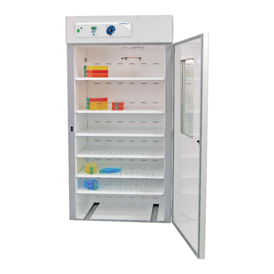
Section INSTALLATION Local city, county or other ordinances may govern the use of this equipment. If you have any questions about local requirements, please contact the appropriate local agency. Installation may be performed by the end user. Under normal circumstances this unit is intended for use indoors, at room temperatures between 5 and 40C, at no greater than 80% Relative Humidity (at 25C) and with a supply voltage that does not vary by more than 10%. - Page 5 Place shelves into chamber at desired position. See Figure 1. Figure 1...
-
Page 6: Graphic Symbols
Section GRAPHIC SYMBOLS Your incubator is provided with a display of graphic symbols on the control panel which are designed to help identify the use and function of the adjustable components. Indicates that you should consult your manual for further description and discussion of a control or user item. -
Page 7: Control Overview
Section CONTROL PANEL OVERVIEW Power Switch: The main power I/O (on/off) switch controls all power to the unit and must be in the I/ON position before any systems are operational. Main Temperature Control: The Main Temperature Control consists of the digital display and UP/DOWN arrow pads for inputting set point temperatures and calibration. -
Page 8: Operation
Section OPERATION Check power supply against unit data plate, they must match. Plug service cord into the grounded electrical outlet, and turn the unit on. Turn the Overtemperature Thermostat to its maximum position, clockwise, using a coin or a flat edged tool. -
Page 9: Chart Recorder Installation
Section CHART RECORDER INSTALLATION Please note that the following information is a general guide for installation. Chart recorders are available from your dealer. Before attempting installation please read the instructions provided with your chart recorder thoroughly for specific installation instructions. Note: Unplug unit from the power supply before installing the Chart Recorder. -
Page 10: Maintenance
Section MAINTENANCE NOTE: Disconnect the power cord from the power source before performing any service or maintenance on this unit. Cleaning: Clean the incubator interior and remove and clean shelves on a regular basis. Use a disinfectant that is suitable for your application. A thorough periodic cleaning is strongly recommended. -
Page 11: Troubleshooting
Section TROUBLESHOOTING FOR PERSONAL SAFETY, ALWAYS DISCONNECT THE POWER BEFORE SERVICING. Always make a visual inspection of the incubator and control panel when troubleshooting. Look for loose or disconnected wires that may be the source of trouble. TEMPERATURE Temperature too high-display and reference thermometer don’t match 1/ Controller set too high-see section 5.5. - Page 12 Unit will not heat up at all 1/ Verify that controller is asking for heat by looking for HEATING light – if pilot light is not on continuously during initial start up, there is a problem with the controller. 2/ Check amperage – amperage should be virtually at maximum rated (data plate) amperage.
- Page 13 motor. 2/ If shaft rubs or is frozen, relieve binding and retest. Motor makes noise 1) Make sure that the fan or blower wheel is not contacting its housing. Adjust the motor mounting bracket position to re-center the fan or blower wheel, if necessary.
-
Page 14: Parts List
2600535 2600535 Circuit Breaker 1100505 1100505 Cord Set 1800529 1800537 Cord set, European 1800541 EMI Filter, CE units only 2800502 Heating Element, 1915 2350563 2350554 Heating Element, 1925 2350557 2350566 Overtemperature Thermostat 1750862 1750813 I/O (On/Off) Power Switch 7850570 7850570... -
Page 15: Unit Specifications
UNIT SPECIFICATIONS Weight Shipping 1915 610 lbs. 500 lbs. 1925 730 lbs. 850 lbs. Dimensions Exterior WxDxH Interior WxDxH 1915 37x33x75 30.5x26x62 1925 41x34x87 35x26x76.5 Capacity 1915 28 Cubic Feet 1925 40 Cubic Feet Temperature Range Uniformity Sensitivity 1915 Amb. +8 to 70C + .5C @ 37... - Page 16 WIRE DIAGRAM 1915 100-120V (9851182) 1800529 115V POWER CORD HARD WIRED 1100505 CIRCUIT BREAKER 15A MAIN POWER SWITCH GREEN LIGHTED 7850570 CHAMBER FAN ~ 4880548 ½ TB1 ½ TB1 TEMPERATURE NEUTRAL CONTROL 1750982 GROUND LOAD OTP LIGHT 4650553 BLK HT...
- Page 17 WIRE DIAGRAM 1915-2 220-240V (9851184) POWER CORD 1800537 CURCUIT BREAKER CURCUIT BREAKER 1100505 1100505 MAIN POWER SWITCH GREEN LIGHTED 7850570 CHAMBER FAN ~ 4880548 ½ TB1 ½ TB1 BLU & BLK TEMPERATURE NEUTRAL CONTROL 1750983 GROUND LOAD 0900503 OTP LIGHT 4650553 0.47 F / 250 VAC...
- Page 18 WIRE DIAGRAM 1925 100-120V (9851181) 1800529 115V POWER CORD HARD WIRED 1100505 CIRCUIT BREAKER 15A MAIN POWER SWITCH GREEN LIGHTED 7850570 CHAMBER FAN ~ 4880548 ½ TB1 ½ TB1 TEMPERATURE NEUTRAL CONTROL 1750982 GROUND LOAD OTP LIGHT 4650553 BLK HT WHT HT 0900503 DESIGN = 1000W 12.4...
- Page 19 WIRE DIAGRAM 1925-2 220-240V (9851183) POWER CORD 1800537 CURCUIT BREAKER CURCUIT BREAKER 1100505 1100505 MAIN POWER SWITCH GREEN LIGHTED 7850570 CHAMBER FAN ~ 4880548 ½ TB1 ½ TB1 BLU & BLK NEUTRAL TEMPERATURE CONTROL 1750983 GROUND LOAD 0900503 OTP LIGHT 4650553 0.47 F / 250 VAC BLK HT WHT HT...
- Page 20 SHELDON MANUFACTURING, INC. LIMITED WARRANTY Sheldon Manufacturing, Inc., (“Manufacturer”) warrants for the original user of this product in the U.S.A. only that this product (parts only if outside of the U.S.A.) will be free from defects in material and workmanship for a period of two years from the date of delivery of this product to the original user (the “Warranty Period”).
- Page 21 Edmonton, Alberta San Diego, CA Lake Charles, LA S. Plainfield, NJ SAN DIMAS, CA Or Call Direct for Specialized Service Locations: VWR International Switzerland VWR Furniture Division 3000 Hadley Rd Ruchligstrasse # 20 P.O. Box 3405 S. Plainfield, NJ 07080 P.O.
Need help?
Do you have a question about the 1915 and is the answer not in the manual?
Questions and answers