Table of Contents
Advertisement
Quick Links
Installation Manual
Use this manual for circuit board 1601-010 Revision W or higher.
INSTALLATION AND USE OF THE LANE BARRIER IN AREAS SUBJECT TO FREEZING WEATHER WITH POTENTIAL FOR
SNOW AND ICE ACCUMULATION IS NOT RECOMMENDED.
THIS PRODUCT IS TO BE INSTALLED AND SERVICED BY A TRAINED GATE/DOOR SYSTEMS TECHNICIAN ONLY.
Visit www.doorking.com/dealer-locator to find a professional installing and servicing dealer in your area.
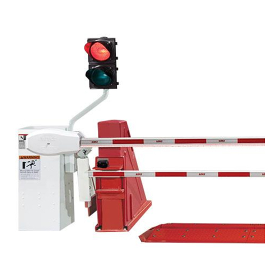
The 1620 lane barrier is not a stand-alone product. It must be used with
a 1603-580 Barrier Gate Operator (sold separately). The 1620 is not crash
UL 325 Compliant
rated. It is intended to provide a more formidable barrier in conjunction
with a standard barrier arm operator system. The 1620 is ideally used to
control passenger vehicles and lightduty trucks.
Surface Mount Vehicular Lane Barrier Accessory
IMPORTANT: Installation of Traffic Light, Photocell
and Octagon Arm with LED Edge is REQUIRED.
®
Copyright 2021 DoorKing
, Inc. All rights reserved.
1620 Lane Barrier
1620 Lane Barrier
1620 Lane Barrier
1620 Lane Barrier
1620-065-K-11-21
G
G
G
,
,
NI
NG
NG
RM
ca
M
can
M
can
M
ge
g
ge
. .
.
W AR
VI NG
AR
AR
AR
AR
e da
d
m
da
ma
da
da
ma
ma
r d
r de
r de
ath
ath
a
de
de
ath
icl
or
MO
se
s inj
veh
ury
arm
m
m
m
cau
iou
EA
R
of
ser
CL
ST
AY
tim
es.
ian
s
all
de
str
at
:
Pe
ycl
es
les
NO
Bic
tor
cyc
Mo
53382
CONFORM
325
S TO
ANSI/UL-
CERTIFIE
C22.2
TO
NO.
D
247
CAN/CSA
OR
HP
GATE
AR
OPERAT
VEHICUL
CLASS
MODEL
PHASE
SERIAL
60
Hz
VOLTS
AMPS
MAX
GATE
LOAD
Inglewood
, CA
DoorKing,
Inc.,
s e
a u
n C
a th
C a
D e
e
a te
o r
y tim
an
g G
ry
e at
In ju
pl ay
v in
m ov
M o
u s
m ay
te
or
at e
e ga
ri o
S e
! G
.
e th
AR
ni ng
er at
ly .
e.
LE
w ar
op
nc
P C
io r
re n
on
en
tra
K EE
t pr
ild
hi cl
es
ra te
ou
t ch
.
w ith
t le
ar ea
fo r
e se
ve
pa
no
te
e is
D o
ga
t us
th e
nc
us
in
tra
s m
is
en
tri an
Th
P ed
es
Advertisement
Table of Contents

Related Manuals for DoorKing 1620


Summary of Contents for DoorKing 1620
- Page 1 ® Copyright 2021 DoorKing , Inc. All rights reserved. The 1620 lane barrier is not a stand-alone product. It must be used with a 1603-580 Barrier Gate Operator (sold separately). The 1620 is not crash UL 325 Compliant rated. It is intended to provide a more formidable barrier in conjunction with a standard barrier arm operator system.
-
Page 3: Table Of Contents
Lane Arm Installation Attachment Lane Arm Rod Attachment Install Traffic Light (Required) 10-11 Install Octagon Arm with Reverse/LED Edge 12-13 Entry Lane Only In-Ground Loop Options Install Photocell (Required) Manual Release Operation Operator Factory Wiring and ALL Components Wiring 1620-065-K-11-21... - Page 4 DoorKing Safety for Lane Barrier • DKS Lane Barrier System is NOT crash rated. It is intended to provide a formidable barrier to help prevent passenger vehicles and light-duty trucks from driving through a controlled traffic lane. • Lane barrier MUST have reverse/LED edge on arm, traffic light and photoelectric cell functioning or remove...
- Page 5 I N G L a n 1620-065-K-11-21...
-
Page 6: Lane Barrier One-Way Operation
MODEL PHASE SERIAL VOLTS AMPS GATE LOAD DoorKing, Inc., Inglewood, a th a te y tim vi n In ju y mo ri o e en wi tho t let e se e is s mu L a n 1620-065-K-11-21... -
Page 7: Lane Barrier Overview
AMPS 60 Hz MAX GATE LOAD DoorKing, Inc., Inglewood, CA Class of Operation - Model 1601 - UL 325 Class II, III, IV – ETL Listed Type of Gate - Single Traffic Lane Vehicular Barrier Gate Only Arm Type & Length - 14 Ft. Octagon Aluminum... -
Page 8: Ft Layout
15’ 3” damages or injuries caused Right Hand Mount thereby. Traffic Direction • DoorKing, Inc. does not 2’ 2’ assume responsibility or 10’ liability for the installation and unauthorized changes to the 9’ 10” with Covers Installed 2’... -
Page 9: Ft Layout
19’ 3” damages or injuries caused Right Hand Mount thereby. Traffic Direction • DoorKing, Inc. does not 2’ 2’ assume responsibility or 14’ liability for the installation and unauthorized changes to the 13’ 10” with Covers Installed 2’... -
Page 10: Lane Arm Installation
S i d e t e r l a n 5 ” I n s l t s t a l l a t s e m i o n b l y 5 ” l t s 1620-065-K-11-21... -
Page 11: Attachment
MODEL SERIAL VOLTS PHASE AMPS 60 Hz MAX GATE LOAD DoorKing, Inc., Inglewood, CA Lane Arm (Up Position) Moving Gate Can Cause Secure support Serious Injury or Death posts to the KEEP CLEAR! Gate may move at any time Cut off excess threads flush without prior warning. -
Page 12: Install Traffic Light (Required)
2” conduit nut to secure elbow. 2” Elbow Make sure traffic light stays clear of raising arm. Arm Up Arm Down See next page Top View to wire traffic light. 1620-065-K-11-21... - Page 13 L - Line NOTE: Power supply MUST removed Transformer 8.5 amp BEFORE terminal can be accessed. SUPPLY GROUND N - Neutral Transformer 8.5 amp Ground Green Panel Stud Ground Transformer 8.5 amp Required Keep wire clear of all moving parts. 1620-065-K-11-21...
-
Page 14: Install Octagon Arm With Reverse/Led Edge
Plug in reverse edge. Red/Blue plugs NOT used. Use bottom hole on arm bracket to secure cable grip. IMPORTANT: Allow slack in the wire harness between the cable grips of at least 13” or more for the rotating arm. 1620-065-K-11-21... - Page 15 DoorKing Part Numbers Install Reverse/LED Edge on Octagon Arm 8080-080 Reverse Edge Install on a 14 ft aluminum octagon arm for a 1601 barrier gate operator. 8080-096 Note: DO NOT operate arm with a malfunctioning reverse edge. Reverse Edge + Red/Green LED...
-
Page 16: Entry Lane Only In-Ground Loop Options
It is recommended that a licensed electrical contractor perform this work. Switch 4 is ON. Loop detector wiring shown is for DoorKing model 9409 Dual Channel plug-In loop detector only. Switch 7 is OFF (Timer). The arm... -
Page 17: Install Photocell (Required)
SW 2 B) Other cable with equivalent or better electrical, mechanical, and flammability ratings. REVERSE 1601-010 SENSITIVITY Terminal #5 Note: DoorKing Retro-Reflective Exceeding 250 mA DOWN Photocell (P/N 8080-057) LOOP of power from this terminal may cause If using other photocells refer the circuit board to the manufacturer’s manual... -
Page 18: Manual Release Operation
C r a r a g h il h ic a r e w it t le f o r e is S t o t h e t r a ia n s t r 1620-065-K-11-21... -
Page 19: Operator Factory Wiring And All Components Wiring
Breakaway Sensor Blue Plugs Blue Connector Required Battery Backup C8 L9 Pink Breakaway Sensor Blue Connector Used Battery BackUp C9 L10 Yellow DoorKing Retro-Reflective Traffic Photocell (P/N 8080-057) Up Limit Magnet Light TIME DELAY White Magnetic Red/ LOOP Limit Sensor... - Page 20 INSTALLATION AND USE OF THE LANE BARRIER IN AREAS SUBJECT TO FREEZING WEATHER WITH POTENTIAL FOR SNOW AND ICE ACCUMULATION IS NOT RECOMMENDED. THIS PRODUCT IS TO BE INSTALLED AND SERVICED BY A TRAINED GATE/DOOR SYSTEMS TECHNICIAN ONLY. Visit www.doorking.com/dealer-locator to find a professional installing and servicing dealer in your area. www.doorking.com DoorKing, Inc.
Need help?
Do you have a question about the 1620 and is the answer not in the manual?
Questions and answers