Table of Contents
Advertisement
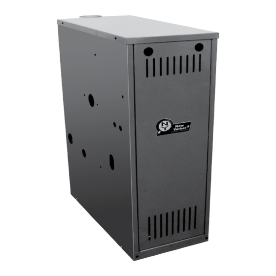
Installation, Operating and Service Instructions for
CG-F
Models:
• CG20F
• CG30F
• CG40F
• CG50F
• CG60F
• CG70F
• CG80F
• CG90F
Manual Contents
1.
Dimensional and Physical Data . . . . . . . . . . . . .3
2.
Pre-Installation . . . . . . . . . . . . . . . . . . . . . . . . . .5
3.
Removing Existing Boiler . . . . . . . . . . . . . . . . .6
4.
Unpack Boiler . . . . . . . . . . . . . . . . . . . . . . . . . . .6
5.
Venting . . . . . . . . . . . . . . . . . . . . . . . . . . . . . . . . .7
6.
Water Piping . . . . . . . . . . . . . . . . . . . . . . . . . . .10
7.
Gas Piping . . . . . . . . . . . . . . . . . . . . . . . . . . . . .13
8.
Electrical . . . . . . . . . . . . . . . . . . . . . . . . . . . . . .14
9. System Start-up and Checkout . . . . . . . . . . . .18
10. Operation . . . . . . . . . . . . . . . . . . . . . . . . . . . . . .23
11. Before Leaving Jobsite . . . . . . . . . . . . . . . . . . .27
12. Service and Maintenance . . . . . . . . . . . . . . . .28
13. How it Works . . . . . . . . . . . . . . . . . . . . . . . . . . .32
14. Troubleshooting . . . . . . . . . . . . . . . . . . . . . . . .34
15. Service Parts . . . . . . . . . . . . . . . . . . . . . . . . . .39
Appendix . . . . . . . . . . . . . . . . . . . . . . . . . . . . . . . . .46
TO THE INSTALLER:
Affix these instructions adjacent to boiler.
Provide model number and serial number when
seeking information and support.
TO THE CONSUMER:
Retain these instructions for future reference.
Contact heating contractor for all issues and support.
Improper installation, adjustment, alteration, service, or maintenance can cause property damage, injury,
or loss of life. For assistance or additional information, consult a qualified installer, service agency or gas
supplier. Read these instructions carefully before installing.
110118-02 2/21
TM
Page
!
• Water Boiler
• Cast Iron
• Chimney Vent
• Gas Fired
WARNING
9700609
Advertisement
Table of Contents

Subscribe to Our Youtube Channel
Related Manuals for New Yorker CG20F


Summary of Contents for New Yorker CG20F
-
Page 1: Table Of Contents
Installation, Operating and Service Instructions for CG-F • Water Boiler • Cast Iron • Chimney Vent • Gas Fired Models: • CG20F • CG30F • CG40F • CG50F • CG60F • CG70F • CG80F • CG90F Manual Contents Page Dimensional and Physical Data ... . .3 Pre-Installation . - Page 2 Installation, Operating & Service Manual CG-F The City of New York requires a Licensed Master Plumber supervise the installation of this product. The Massachusetts Board of Plumbers and Gas Fitters has approved the CG-F™ Series Boiler. See the Massachusetts Board of Plumbers and Gas Fitters website, http://licensing.reg.state.ma.us/pubLic/pl_products/ pb_pre_form.asp for the latest Approval Code or ask your local Sales Representative.
-
Page 3: Dimensional And Physical Data
Supply NPT Return NPT Vent Gas NPT Relief Valve Drain Depth Width Height Model (inch) (inch) (inch) (inch) NPT (inch) NPT (inch) CG20F 1 ¼ 1 ¼ ½ ¾ ¾ CG30F 1¼ 1¼ ½ ¾ ¾ CG40F 1¼ 1¼ ½... - Page 4 Installation, Operating & Service Manual CG-F Dimensional and Physical Data (continued) Model CG20F 14" CG30F 14" CG40F 16" CG50F 19" CG60F 22" CG70F 25" CG80F 28" Figure 1-3: Minimum Closet Clearances Model CG90F 31" Figure 1-4: Minimum Alcove Clearances Minimum radial clearance around vent pipe and breeching for single-wall metal pipe vent connector.
-
Page 5: Pre-Installation
Installation, Operating & Service Manual CG-F Pre-Installation WARNING WARNING Carefully read all instructions before installing ASSURE THAT THE FRONT AIR DAM is in place boiler. Failure to follow all instructions in proper and undamaged. A damaged front air dam will order can cause personal injury or death. -
Page 6: Removing Existing Boiler
Installation, Operating & Service Manual CG-F Removing Existing Boiler A. If an Existing Boiler is Removed: 4. Place in operation the appliance being inspected. Follow the Lighting (or Operating) When an existing boiler is removed from a Instructions. Adjust thermo stat so appliance common venting system, the common venting will operate continuously. -
Page 7: Venting
Installation, Operating & Service Manual CG-F Venting The CG-F Series boiler is a Category I, draft hood A. Inspect chimney and remove any obstructions equipped appliance. or restric tions. Clean chimney if previously used for solid or liquid fuel-burning appliances or 1. - Page 8 Installation, Operating & Service Manual CG-F Venting (continued) 4. Vent pipe to chimney must not be smaller than outlet on draft hood or vent damper. Arrange venting system so boiler is served by vent damper device. Exception: National Fuel Gas Code, ANSI Z223.1/NFPA 54, and allow vent downsizing when vent size determined by their Vent Sizing...
- Page 9 Installation, Operating & Service Manual CG-F Venting (continued) Install vent termination (Masonry chimney and 2. For terminations located at least 8 ft. from single wall metal pipe) vertical wall or similar obstruction, termination shall extend above roof in accordance with 1.
-
Page 10: Water Piping
Installation, Operating & Service Manual CG-F Water Piping D. Connect system supply and return piping to boiler. WARNING Refer to Figures 6-1, 6-2, and 6-3. Also consult Failure to properly pipe boiler may result in Residential Hydronic Heating Installation and Design improper operation and damage to boiler or I=B=R Guide. - Page 11 Installation, Operating & Service Manual CG-F Water Piping (continued) 110118-02 2/21...
- Page 12 Installation, Operating & Service Manual CG-F Water Piping (continued) 110118-02 2/21...
-
Page 13: Gas Piping
Installation, Operating & Service Manual CG-F Gas Piping A. Size gas piping. Design system to provide adequate gas supply to boiler. Consider these factors: 1. Allowable pressure drop from point of delivery to boiler. Maximum allowable system pressure is ½ psig. Minimum gas valve inlet pressure is listed on rating label. -
Page 14: Electrical
Installation, Operating & Service Manual CG-F Electrical D. For installations using zone valves, provide separate WARNING transformer for zone valve wiring. Consult zone valve Electrical Shock Hazard. Wiring errors can manufacturer for assistance. See Figure 8-3. cause improper or dangerous operation. Verify proper operation after installation. - Page 15 Installation, Operating & Service Manual CG-F Electrical (continued) Figure 8-1: Wiring Connection Diagram 110118-02 2/21...
- Page 16 Installation, Operating & Service Manual CG-F Electrical (continued) Figure 8-2: Schematic Ladder Diagram 110118-02 2/21...
- Page 17 Installation, Operating & Service Manual CG-F Electrical (continued) Figure 8-3: Wiring Schematic, Zone Valves Figure 8-4: Wiring Schematic, Zone Circulators 110118-02 2/21...
-
Page 18: System Start-Up And Checkout
Installation, Operating & Service Manual CG-F System Start-up and Checkout A. Visual Main Burner Check D. Purge Air from System Inspect burners for dislodgement during 1. Fill entire heating system with water and shipment. Rear of burners should be in vertical vent air from boiler, radiators and system, slots in rear of burner tray and front of burners one zone at a time. - Page 19 Installation, Operating & Service Manual CG-F System Start-up and Checkout (continued) Figure 9-2: Operating Instructions 110118-02 2/21...
- Page 20 Installation, Operating & Service Manual CG-F System Start-up and Checkout (continued) 3. Locate and address leaks using listed E. Perform gas leak test upstream of boiler shutoff combustible gas detector,a non corrosive leak valve. detection fluid or other listed leak 1.
- Page 21 Do not install at elevations above 12,000 ft. See Table below. Input (MBH) Boiler Rating 10,000 5,000 ft. 7,000 ft. Model Label CG20F 30.5 27.5 CG30F Figure 9-6: Main Burner Flame CG40F CAUTION CG50F Avoid operating boiler in an environment where CG60F...
- Page 22 Installation, Operating & Service Manual CG-F System Start-up and Checkout (continued) P. Check ignition system safety shut-off device. After control has finished sparking, remove ignitor/ flame sense wire from control. Burners will shut down. Q. Test LWCO functionality Press "TEST" button on IDL 1200. See Figure 9-1. Boiler should shut down.
-
Page 23: Operation
Installation, Operating & Service Manual CG-F Operation Table 10-1: Sequence of Operation A. Boiler Sequence of Operation (See Table 10-1) 1. When thermostat calls for heat, control starts Status Codes displayed in STA Mode system circulator. Status Description Standby 2. If thermostat is not satisfied with residual (Burner off No call for heat detected heat in boiler, or boiler water temperature is... - Page 24 Installation, Operating & Service Manual CG-F Operation (continued) Viewing the Operating Mode Options In operating mode, user may view (but Table 10-3: Adjustable Parameters not change) boiler operating status, settings and Default Range Description troubleshooting information. 180oF 140-220°F Adjust High Limit Setting For example, when “I ”...
- Page 25 Installation, Operating & Service Manual CG-F Operation (continued) More Information About Adjustable Parameters Table 10-5: Circulator Pre-purge Time example, 1. High Limit (HL_) (PP_ = 2 minutes) Burner turns "off" when boiler water temperature (bt) is above this value. Call for Boiler Heat Terminal...
- Page 26 Installation, Operating & Service Manual CG-F Operation (continued) 7. Domestic Hot Water (DHW) Terminal Function (dh_) b. Second heating zone (dh_ is set to second heating zone (tt2)) DHW Circulator output can be connected to a domestic hot water circulator or a second Helpful when home uses only two heating heating zone circulator.
-
Page 27: Before Leaving Jobsite
Installation, Operating & Service Manual CG-F Before Leaving Jobsite Before Leaving Jobsite: Boiler and system filled with water Performed gas leak test Checked pilot burner flame Checked main burner flames Checked gas input rate Checked gas inlet pressure ... -
Page 28: Service And Maintenance
Installation, Operating & Service Manual CG-F Service and Maintenance Important Product Safety Information: Refractory Ceramic Fiber Product WARNING Some boiler components use materials that contain refractory ceramic fibers (RCF). RCF has been classified as a possible human carcinogen. When exposed to elevated temperatures, RCF may change into crystalline silica, a known carcinogen. - Page 29 Installation, Operating & Service Manual CG-F Service and Maintenance (continued) WARNING Service on this boiler should be undertaken only by trained and skilled personnel from a qualified service agency. Inspections should be performed at intervals specified in this manual. Maintain manual in a legible condition.
- Page 30 Installation, Operating & Service Manual CG-F Service and Maintenance (continued) Inspect Temperature/Pressure Gauge D. Clean Main Burners and Firebox. 1. Water temperature needle should move with 1. To remove burners for cleaning, changing variation in water temperature. orifices, or repairs: 2.
- Page 31 Installation, Operating & Service Manual CG-F Service and Maintenance (continued) Q. Test Vent Damper Operation Vent damper must be in open position when main burners are operating. R. Test Functionality of LWCO See "Start-up and Checkout - Check LWCO Functionality. S.
-
Page 32: How It Works
Installation, Operating & Service Manual CG-F How It Works CG-F boilers are equipped with an Intelligent Hydronic Control. This control combines features such as ignition control, high limit switch, and circulator relays. Energy is saved by using a thermal purge feature that starts the circulator and delays burner start when residual heat is available in boiler. - Page 33 Installation, Operating & Service Manual CG-F How It Works (continued) Rear of Boiler (On rear of boiler) UNLESS OTHERWISE N ALL DIMENSIONS IN IN TOLERANCES: X.X ±.1 X.XXX ±.0 X.XX ±.03 ANGLE PROP U.S. Boiler C LANC THIS DOCUMENT CONTAIN AND ITS CONTENTS ARE TH COMPANY, INC.
-
Page 34: Troubleshooting
Installation, Operating & Service Manual CG-F Troubleshooting A. Before Troubleshooting B. IDL 1200 LWCO: Amber "LOW WATER" LED indicates the boiler is not sensing water in boiler. When using troubleshooting tables, keep in mind: 1. If AMBER LED is ON and boiler is filled with 1. - Page 35 Installation, Operating & Service Manual CG-F Troubleshooting (continued) C. Use Control Display ERR (ERROR) Number To Direct TroubleShooting Efforts If control detects an error it will flash “Err” (ERROR) followed by a number. Use this number to identify boiler problem and corrective action in table below. If there is no Err display, proceed to Troubleshooting Section D: Display Status Recommended Corrective Action...
- Page 36 Installation, Operating & Service Manual CG-F Troubleshooting (continued) D. Use STA (STATUS) Number To Guide Troubleshooting The control will flash “STA” followed by a number. Use this number to identify the boiler problem in table below: 1. Boiler and Circulator Off Display / Status Recommended Corrective Action Boiler has not detected a call for heat (tt = ff and dh = ff).
- Page 37 Installation, Operating & Service Manual CG-F Troubleshooting (continued) 5. Circulator is On But Damper is Not Open Display / Status Recommended Corrective Action Control is waiting for damper to open. Damper end switch has failed to close (end switch contact is stuck open). Combustion can never take place unless damper blade is in the fully open position.
- Page 38 Installation, Operating & Service Manual CG-F Troubleshooting (continued) 6. Circulator is On, Damper is Open But Boiler Fails to Start (continued) Display / Status Recommended Corrective Action 1. No Spark a. Can you hear sparking while STA 6 is displayed? - If there is no spark noise, replace the control.
-
Page 39: Service Parts
CG-F Service Parts All CG-F Series Repair Parts may be obtained through New Yorker Boiler Company, Inc. or its authorized distributors. Should you require assistance in locating a New Yorker Distributor in your area, or have questions regarding the availability of New Yorker Boiler Company products or repair parts, please contact New Yorker Customer Service at New Yorker Boiler Company, Inc., P.O. - Page 40 Installation, Operating & Service Manual CG-F Service Parts (continued) Part Number [Quantity] Description CG20F CG30F CG40F CG50F CG60F CG70F CG80F CG90F Base Wrapper Base Tray Burner Tray Base Side Insulation Base Rear Insulation Base Front Insulation Drip Shields Manifold Support...
- Page 41 Installation, Operating & Service Manual CG-F Service Parts (continued) Natural Gas Only Part Number [Quantity] Description CG20F CG30F CG40F CG50F CG60F CG70F CG80F CG90F Gas Valve (Natural Gas), 109620-01 [1] Honeywell VR8204C3007 Gas Valve (Natural Gas), 109622-01 [1] Honeywell VR8304P4496...
- Page 42 Installation, Operating & Service Manual CG-F Service Parts (continued) Part Number [Quantity] Key No. Description CG20F CG30F CG40F CG50F CG60F CG70F CG80F CG90F Control 103966-02 [1] Transformer 106034-01 [1] Temperature Sensor/LWCO 106495-02 [1] 110118-02 2/21...
- Page 43 Installation, Operating & Service Manual CG-F Service Parts (continued) Part Number [Quantity] Description CG20F CG30F CG40F CG50F CG60F CG70F CG80F CG90F Jacket Wrap-around Jacket Panel Jacket Vestibule Panel Jacket Rear Discharge Chute 106707-02 [1] 106707-03 [1] 106707-04 [1] 106707-05 [1] 106707-06 [1] 106707-07 [1] 106707-08 [1]...
- Page 44 Installation, Operating & Service Manual CG-F Service Parts (continued) Part Number [Quantity] Description CG20F CG30F CG40F CG50F CG60F CG70F CG80F CG90F Supply Water Manifold 109614-01 [1] Temperature/Pressure Gauge 105894-01 [1] 30 PSI Relief Valve 109038-01 [1] Drain Valve Obtain Locally (3/4" NPT boiler connection)
- Page 45 Installation, Operating & Service Manual CG-F Service Parts (continued) Part Number [Quantity] Key No. Description CG20F CG30F CG40F CG50F CG60F CG70F CG80F CG90F Power Supply Harness 109639-01 [1] Main Control Harness 109640-01 [1] Accessories: Part Number [Quantity] Key No. Description...
-
Page 46: Appendix
Installation, Operating & Service Manual CG-F Appendix: Combination Refrigeration/ Heating System A. If boiler is used in connection with refrigeration B. If boiler is connected to heating coils located in systems, boiler must be installed with chilled air handling units where they may be exposed to medium piped in parallel with the heating boiler refrigerated air, boiler piping must be equipped using appropriate valves to prevent chilled... - Page 47 Water temperatures below 120oF cause condensation that damage cast iron, burners and other components. This is not unique to New Yorker Boiler designs. All cast iron boilers act the same way. Typical high temperature [170oF and higher] fin tube radiation heating systems will have short condensation cycles in 'shoulder' seasons, early and late parts of the heating season.
- Page 48 Installation, Operating & Service Manual CG-F Appendix: Low Return Water Temperatures (continued) Primary-Secondary Pumping: This is an improvement over simple by-pass piping to reduce condensation. Again this is a fixed system. It can not adapt to variations in temperature and flow. Best Alternative: System by-pass kit [part number 107795-01] that addresses these situations.
- Page 49 Installation, Operating & Service Manual CG-F SERVICE RECORD DATE SERVICE PERFORMED 110118-02 2/21...
- Page 50 Installation, Operating & Service Manual CG-F SERVICE RECORD DATE SERVICE PERFORMED 110118-02 2/21...
- Page 51 Installation, Operating & Service Manual CG-F SERVICE RECORD DATE SERVICE PERFORMED 110118-02 2/21...
- Page 52 Installation, Operating & Service Manual CG-F SERVICE RECORD DATE SERVICE PERFORMED 110118-02 2/21...
Need help?
Do you have a question about the CG20F and is the answer not in the manual?
Questions and answers