NuTone AVDF1 Series Installation Use And Care Manual
Hide thumbs
Also See for AVDF1 Series:
- User manual ,
- Installation use and care manual (78 pages) ,
- Additional information (7 pages)

Related Manuals for NuTone AVDF1 Series


Summary of Contents for NuTone AVDF1 Series
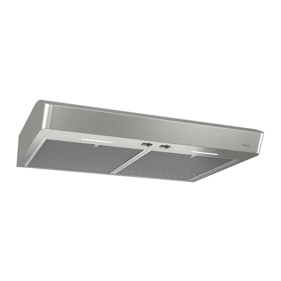
- Page 1 WWW.NUTONE.COM WWW.NUTONE.CA RANGE HOOD Series: AVDF1, AVSF1 and AVSF1-2 INSTALLATION, USE AND CARE MANUAL Serial number: 99045654-002H...
-
Page 2: Table Of Contents
Safety ....... . . 3-4 Operation ....... 5 Cleaning and Maintenance . -
Page 3: Safety
READ AND SAVE THESE INSTRUCTIONS Intended for domestic cooking only INSTALLER: LEAVE THIS MANUAL WITH HOMEOWNER. In U.S.A., register your range hood online at www.nutone.com In Canada, register your range hood online at www.nutone.ca WARNING TO REDUCE THE RISK OF FIRE, ELECTRIC SHOCK, OR INJURY TO PERSONS, OBSERVE THE FOLLOWING: •... - Page 4 WARNING TO REDUCE THE RISK OF A RANGE TOP GREASE FIRE: a) Never leave surface units unattended at high settings. Boilovers cause smoking and greasy spillovers that may ignite. Heat oils slowly on low or medium settings. b) Always turn hood ON when cooking at high heat or when flambeing food (i.e.: Crêpes Suzette, Cherries Jubilee, Peppercorn Beef Flambé).
-
Page 5: Operation
Turns light OFF. Turns blower OFF. Turns blower on to HIGH speed. AVDF1 SERIES BLOWER BUTTON When blower is OFF, press this button to turn ON the blower at the last saved speed. If there was no speed saved, the blower will be set on LOW speed. -
Page 6: Cleaning And Maintenance
Cleaning and Maintenance Proper maintenance of the Range Hood will assure proper performance of the unit. MOTOR The motor is permanently lubricated and never needs oiling. If the motor bearings make excessive or unusual noise, replace the motor with the exact service motor. The fan blade should also be replaced. -
Page 7: Installation
For ADA compliance installation guidelines, please visit www.broan-nutone.com Recommended Tools and Accessories for Installation • Measuring tape • Phillips screwdriver no. 2 • Flat blade screwdriver (to open knockout holes) • Drill, 1/8” drill bit and 1½” hole saw (to mark holes for ducting and cut electrical access hole) •... -
Page 8: Contents
Contents Before proceeding to the installation, check the contents of the box. If items are missing or damaged, contact the manufacturer. Make sure that the following items are included: AVDF1 and AVSF1-2 Series AVSF1 Series IND INSIDE IND INSIDE OF HOOD OF HOOD (1) 3¼”... -
Page 9: Prepare The Hood
Prepare the Hood NOTE: Since this manual covers many range hood models, some details in the following illustrations may sligthly differ from your unit. 1 ] If present, remove all protective polyfilm from the hood and/or parts. 2 ] Using the finger cup (AVDF1, AVSF1-2 Series) or the tab (AVSF1 Series), remove the grease ... - Page 10 5 ] Remove 7” Round Duct Plate from top/back of hood (see illustration below). Keep the screws for further use. 7” ROUND DUCT PLATE 2 SCREWS 6 ] Remove Electrical Power Cable Knockout from top (vertical exhaust) or back (horizontal exhaust) of hood.
- Page 11 DUCTED INSTALLATION ONLY 8 ] Remove 3¼” x 10” vertical, 3¼” x 10” horizontal, or 7-inch round knockout plate as appropriate for your ducting method (see F 1 A and 1 B). IGURES IGURE IGURE 7” ROUND KNOCKOUT PLATE ( ALSO REMOVE VERTICAL KNOCKOUT PLATE 3¼”...
-
Page 12: Prepare The Hood Location
Prepare the Hood Location NOTE: Before starting installation, read all the steps of these instructions. Use the illustration below to identify your kitchen cabinet type. FRAMED CABINET FRAMELESS CABINET This manual covers 2 kinds of installation: the standard (without EZ1 brackets) and the EZ1 one-person installation system (using included template and brackets). - Page 13 4 ] Drill a 1/8” dia. pilot hole for house wiring, at A location on template. 5 ] Use a sharp pencil or 1/8” drill bit to mark the locations for the appropriate duct access holes (16 locations for 7” round duct, or 4 corner locations for rectangular duct). Remove the template.
- Page 14 FRAMELESS CABINET Refer to the marking on brackets to determine the correct installation side and orientation. 7/64” Align the corresponding bracket to the cabinet side, while placing rear end of bracket against the wall. Draw a line on the outer edge of the bracket (as shown). ...
-
Page 15: Install The Hood (Ez1 Bracket)
Install the Hood (EZ1 Bracket) OTE: The following procedure applies to both framed or frameless cabinet installations. 1 ] Run house power cable between service panel and hood location. 2 ] There are 2 pairs of recessed holes on each side of the top of the hood (on rear: A and B, on front C and D on illustration below);... - Page 16 7 ] For framed cabinet, secure the hood to the EZ1 brackets using 4 no. 8-18 x 1/2” metal screws (included in parts bag). Insert 2 screws per side, in the slots (as shown in insets on illustration below). 8 ] For frameless cabinet, secure the hood to the cabinet using 4 no. 8 x 5/8” round head wood screws (included in parts bag).
-
Page 17: Standard Installation
Standard Installation (without EZ1 brackets) 1 ] Use the proper diagram below for placement of ductwork and electrical cutout in cabinet or wall. For a non-ducted installation, DO NOT cut a duct access hole, only cut the hole for electrical wiring. 3¼"... -
Page 18: Install The Hood (Standard Installation)
Install the Hood (Standard Installation) 1 ] Run house power cable between service panel and hood location. Run the house power cable into the hood through the strain relief previously installed in step 6 on page 10. 2 ] Hang hood from (4) mounting screws previously installed. Slide hood back towards wall until mounting screw heads are engaged in narrow end of keyhole slots in top of hood. -
Page 19: Connect The Wiring
Connect the Wiring WARNING Risk of electric shock. Electrical wiring must be done by qualifi ed personnel in accordance with all applicable codes and standards. Before connecting wires, switch power off at service panel and lock service disconnecting means to prevent power from being switched on accidentally. -
Page 20: Wiring Diagrams
Light Switch LED driver input output Motor Switch FAN MOTOR R (Low) BK (High) Line Neutral BN/W Ground AVDF1 SERIES 1 2 3 4 5 6 COLOR CODE BLACK GREEN/YELLOW BLUE ORANGE Override BROWN BN/W BROWN/WHITE WHITE User interface mounted to J10 on back of control board. -
Page 21: Service Parts
ARTS AND EPAIRS In order to ensure your unit remains in good working condition, you must use Broan-NuTone LLC or Venmar Ventilation ULC genuine replacement parts only. Broan-NuTone LLC or Venmar Ventilation ULC genuine replacement parts are specially designed for each unit and are manufactured to comply with all the applicable certification standards and maintain a high standard of safety. - Page 22 ARTS AND EPAIRS In order to ensure your unit remains in good working condition, you must use Broan-NuTone LLC or Venmar Ventilation ULC genuine replacement parts only. Broan-NuTone LLC or Venmar Ventilation ULC genuine replacement parts are specially designed for each unit and are manufactured to comply with all the applicable certification standards and maintain a high standard of safety.
- Page 23 ARTS AND EPAIRS In order to ensure your unit remains in good working condition, you must use Broan-NuTone LLC or Venmar Ventilation ULC genuine replacement parts only. Broan-NuTone LLC or Venmar Ventilation ULC genuine replacement parts are specially designed for each unit and are manufactured to comply with all the applicable certification standards and maintain a high standard of safety.
- Page 24 AVSF1-2 SERIES UANTITY 30" 30" B ART NO ESCRIPTION LACK TAINLESS TAINLESS S97020031 ECIRCULATION COVER PLATE TAINLESS STEEL INCL SCREWS S98011873 ECIRCULATION COVER PLATE LACK TAINLESS INCL SCREWS SR680508 7'' R OUND DUCT PLATE INCLUDING SCREWS S97020534...
-
Page 25: Warranty
Limited Warranty Warranty Period and Exclusions: Broan-NuTone LLC and Venmar Ventilation ULC (either being the “Company”) warrants to the original consumer purchaser of its product (“you”) that the product (the “Product”) will be free from material defects in the Product or its workmanship for a period of one (1) year from the date of original purchase (or such longer period as may be required by applicable law).
Need help?
Do you have a question about the AVDF1 Series and is the answer not in the manual?
Questions and answers