
Related Manuals for SeaLevel UltraCOMM+4.PCIe


Summary of Contents for SeaLevel UltraCOMM+4.PCIe
- Page 1 UltraCOMM+4.PCIe User Manual Item# 7404e Sealevel Systems, Inc. Sealevel.com Phone 864.843.4343...
-
Page 2: Table Of Contents
B - H ........................19 PPENDIX ANDLING NSTRUCTIONS C - E ........................20 PPENDIX LECTRICAL NTERFACE D - A ....................22 PPENDIX SYNCHRONOUS OMMUNICATIONS E – M ........................23 PPENDIX ECHANICAL RAWING ..................................24 ARRANTY ©Sealevel Systems, Inc. 7404e Manual SL9224 02/2017... -
Page 3: Introduction
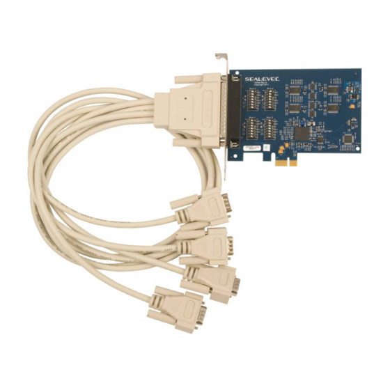
Introduction The Sealevel Ultra COMM+4.PCIe is an four channel RS-232/485/422 PCI express Bus serial I/O adapter supporting data rates up to 921.6Kbps. The RS-232 compatibility allows for connection to devices utilizing the RS-232 electrical interface, such as modems, data-entry terminals, and plotters. -
Page 4: Before You Get Started
Before You Get Started What’s Included The Ultra COMM+4.PCIe is shipped with the following items. If any of these items are missing or damaged, please contact Sealevel for replacement. Ultra COMM+4.PCIe Serial I/O Adapter • • CA143 – DB37 Female to (4) DB9 Male, 36” in length cable Sealevel Software CD •... - Page 5 Depending upon your application, you are likely to find one or more of the following items useful with the Ultra COMM+4.PCIe. All items can be purchased from our website (www.sealevel.com) by calling our sales team at (864) 843-4343. DB9 to DB25 Serial Cable (Item# CA176)
-
Page 6: Card Setup
Choose This Divisor DLM:DLL 1200 bps 3255 2400 bps 1.625 1001 4800 bps 1.750 9600 bps 1.875 19.2K bps 38.4K bps 1.75 57.6K bps 1.825 115.2K bps 1.875 230.4K bps 460.8K bps 2.125 921.6K bps 2.125 ©Sealevel Systems, Inc. 7404e Manual SL9224 02/2017... - Page 7 (i.e. using received characters to throttle the transmitter) or it can confuse the system if the software does not. An RS-485 ‘No Echo’ option is selected by placing both Mode switches (M0, M1) in the ‘On’ position. ©Sealevel Systems, Inc. 7404e Manual SL9224 02/2017...
- Page 8 Figure 2 - RS-422 Mode 1 2 3 4 5 6 7 Figure 3 - RS-485 two-wire with 'Echo' 1 2 3 4 5 6 7 Figure 4 - RS-485 two-wire No 'Echo' ©Sealevel Systems, Inc. 7404e Manual SL9224 02/2017...
-
Page 9: Software Installation
If the media is otherwise unavailable or if desired, the current versions of Sealevel software packages can be obtained from the Sealevel website (see following instructions). If you already have the Sealevel software, proceed to the Windows or Linux installation section. - Page 10 Guided Software Installation 1. Insert the Sealevel media into your PC. 2. If the ‘AutoRun’ feature is enabled for this media the software will automatically launch. 3. Otherwise, navigate to the root directory of the media and double-click the ‘autorun.exe’ application to launch the installation window.
- Page 11 ‘C:\Program Files’ folder on your computer. Some versions of Windows will halt the installation and provide you with a dialog box which will ask you for permission for the installer to make changes to your ©Sealevel Systems, Inc. 7404e Manual SL9224 02/2017...
- Page 12 10. The following dialog box may appear, as shown below. Click the ‘OK’ button to continue. All Sealevel Systems software drivers have been fully tested by Sealevel. Clicking ‘OK’ will not harm your system. 11. The following dialog box may appear, as shown below. Click the ‘OK’ button to continue.
- Page 13 OSs it will be found in the ‘Programs and Features’ list. 3. Navigate to the Device Manager and remove the Sealevel adapter by right clicking on the line item choosing ‘Uninstall’. Depending on your product, it can be found under either ‘Multiport Serial adapters’...
- Page 14 Output RTS+ Request To Send Positive Output RTS- Request To Send Output Negative Receive Data Positive Input Receive Data Negative Input CTS+ Clear To Send Positive Input CTS- Clear To Send Negative Input ©Sealevel Systems, Inc. 7404e Manual SL9224 02/2017...
- Page 15 RTS to CTS and RI. Also, connect DCD to DTR and DSR. Terminating these pins, if not used, will help ensure you get the best performance from your adapter. ©Sealevel Systems, Inc. 7404e Manual SL9224 02/2017...
- Page 16 RTS+ CTS+ The RTS output is only available in RS-232 and RS-422 modes. The RTS output is tri- stated in RS-485 mode and therefore unusable. The CTS input is available in all modes. ©Sealevel Systems, Inc. 7404e Manual SL9224 02/2017...
-
Page 17: Specifications
10 to 90% R.H. Humidity Range Non-Condensing Non-Condensing Manufacturing All Sealevel Systems Printed Circuit boards are built to UL 94V0 rating and are 100% electrically tested. These printed circuit boards are solder mask over bare copper. Power Consumption Supply line +3.3VDC... -
Page 18: Appendixa - Troubleshooting
2. Configure your Sealevel Systems adapter so that there is no conflict with currently installed adapters. No two adapters can occupy the same I/O address. 3. Make sure the Sealevel Systems adapter is using a unique IRQ. While the Sealevel Systems adapter does allow the sharing of IRQs, many other adapters (i.e. SCSI adapters &... -
Page 19: Appendixb - Handling Instructions
• Keep work area free of non-conductive materials such as ordinary plastic assembly aids and Styrofoam. • Use field service tools such as cutters, screwdrivers, and vacuum cleaners that are conductive. ©Sealevel Systems, Inc. 7404e Manual SL9224 02/2017... -
Page 20: Appendixc - Electrical Interface
0 (space) and -12 volts (-3 to -10 volts) denote a binary 1 (mark). The RS-232 and the EIA/TIA-574 specification define two types of interface circuits Data Terminal Equipment (DTE) and Data Circuit-Terminating Equipment (DCE). The Sealevel Systems Adapter is a DTE interface. RS-422 The RS-422 specification defines the electrical characteristics of balanced voltage digital interface circuits. - Page 21 (Tx+ to Rx+ and Tx- to Rx-). Four wire mode allows full duplex data transfers. RS-485 does not define a connector pin-out or a set of modem control signals. RS-485 does not define a physical connector. ©Sealevel Systems, Inc. 7404e Manual SL9224 02/2017...
-
Page 22: Appendixd - Asynchronous Communications
The data rate and communication parameters for asynchronous communications have to be the same at both the transmitting and receiving ends. The communication parameters are baud rate, parity, number of data bits per character, and stop bits (i.e. 9600,N,8,1). ©Sealevel Systems, Inc. 7404e Manual SL9224 02/2017... -
Page 23: Appendixe - Mechanical Drawing
Appendix E – Mechanical Drawing ©Sealevel Systems, Inc. 7404e Manual SL9224 02/2017... -
Page 24: Warranty
We are able to offer this warranty due to our control of manufacturing quality and the historically high reliability of our products in the field. Sealevel products are designed and manufactured at its Liberty, South Carolina facility, allowing direct control over product development, production, burn-in and testing. - Page 25 EUROPEAN COMMUNITY This equipment has been evaluated or tested and found in compliance with the requirements of the following directives issued by the European Commission: • EMC Directive 2014/30/EU • RoHS Directive 2011/65/EU ©Sealevel Systems, Inc. 7404e Manual SL9224 02/2017...
Need help?
Do you have a question about the UltraCOMM+4.PCIe and is the answer not in the manual?
Questions and answers