
Related Manuals for SeaLevel ULTRA 485


Summary of Contents for SeaLevel ULTRA 485
- Page 1 ULTRA 485 USER MANUAL Sealevel Systems, Inc. Phone: (864) 843-4343 155 Technology Place FAX: (864) 843-3067 P.O. Box 830 www.sealevel.com Liberty, SC 29657 USA...
-
Page 2: Table Of Contents
Contents ................ 1 NTRODUCTION ...................1 VERVIEW ’ ................1 NCLUDED ..............1 ACTORY EFAULT ETTINGS ................2 ETUP ................2 DDRESS ELECTION IRQ S ...................3 ELECTION ................4 NTERRUPT ODES RS-485 E ..............5 NABLE ODES ............7 ONNECTOR SSIGNMENTS EIA-530 ..................7 SIO-485 ..................8 ................9 ERMINATION ................ - Page 3 Figure 5 - Header E3 RS-485 Receive Mode ..........6 Figure 6 - DIP-shunt E4 (EIA-530 Mode)............7 Figure 7 - DIP-shunt E4 (SIO-485 Mode)............8 Figure 8 - SW2, Line Termination..............9 Figure 9 - Asynchronous Communications Bit Diagram....... 18 © 1999i Sealevel Systems, Incorporated. All rights reserved.
-
Page 5: Introduction
ULTRA 485 in an RS-485 application with existing (i.e. standard RS-232) software drivers. What’s Included The ULTRA 485 is shipped with the following items. If any of these items are missing or damaged, contact the supplier. •... -
Page 6: Card Setup
Address Selection The ULTRA 485 occupies 8 consecutive I/O locations, and looks to the PC as a standard serial port. A DIP-switch (SW1) is used to set the port address options for the ULTRA 485. Be careful when selecting the port addresses as some selections may conflict with existing ports. -
Page 7: Irq Selection
Any two or more ports can share a common IRQ by placing the jumpers on the same IRQ setting at header E1 and setting the appropriate selections at E2. Consult your particular software for IRQ selection. If no interrupt is desired, remove the jumper. Sealevel Systems ULTRA-485 Page 3... -
Page 8: Interrupt Modes
Figure 2 - Header E2, Normal IRQ Mode Set the jumper to ‘S’ if you are using more than one ULTRA 485 in a bus or to completely remove the pull-down resistor for hardware compatibility. Setting the adapter in this configuration when it is not accompanied by a pull-down resistor will prevent the ports from triggering an interrupt. -
Page 9: Rs-485 Enable Modes
Some communication software packages refer to RS-485 as RTS enable or RTS block mode transfer. One of the unique features of the ULTRA 485 is the ability to be RS-485 compatible without the need for special software or drivers. This ability is especially useful in Windows, Windows NT, and OS/2 environments where the lower level I/O control is abstracted from the application program. -
Page 10: Figure 5 - Header E3 Rs-485 Receive Mode
CTS) are only valid when Header E3 is in the 422 mode. These header blocks are described in the illustration and table that follow. AUTO AUTO Receiver automatically enabled/disabled Receiver enabled by UART RTS signal Receiver always enabled Figure 5 - Header E3 RS-485 Receive Mode Sealevel Systems ULTRA-485 Page 6... -
Page 11: Connector Pin Assignments
Connector Pin Assignments EIA-530 DIP-shunt E4 selects the pin out for the DB-25 connector P3. With the 5 position shunt in the EIA-530 mode, the ULTRA 485 complies with the EIA- 530 pin out with the following signals supported: SIO-485... -
Page 12: Sio-485
Card Setup SIO-485 With the 5-position shunt in the SIO-485 mode, the ULTRA 485 is compatible with the Sealevel Systems SIO-485 (part# 3054) with the following signals supported: EIA-530 SIO-485 Figure 7 - DIP-shunt E4 (SIO-485 Mode) Signal Name Pin #... -
Page 13: Line Termination
DIP-switch SW2 provides the ability to customize this interface to system requirements. Each switch position corresponds to a specific portion of the interface. If multiple ULTRA 485 adapters are configured in a RS-485 network, only the boards on each end should have switches T, P &... -
Page 14: Installation
Refer to the appropriate section of the Serial Utilities Software.System Installation The ULTRA 485 can be installed in any of the PC expansion slots. The ULTRA 485 contains several jumper straps for each port that must be set for proper operation. -
Page 15: Technical Description
16-byte input and output FIFO. A full array of advanced UARTS is also available. The unique feature of the ULTRA 485 is the ability to be RS-485 compatible without the need for special software or drivers. This is especially useful in Windows, Windows NT, and OS/2 environments where the lower level I/O control is abstracted from the application program. -
Page 16: Specifications
Non-Condensing Non-Condensing Manufacturing • All Sealevel Systems Printed Circuit boards are built to U.L. 94V0 rating and are 100% electrically tested. These printed circuit boards are solder mask over bare copper or solder mask over tin nickel. Power Consumption Supply line... -
Page 17: Appendixa - Troubleshooting
No two adapters can occupy the same I/O address. 3. Make sure the Sealevel Systems adapter is using a unique IRQ. The IRQ is typically selected via an on-board header block. Refer to the section on Card Setup for help in choosing an I/O address and IRQ. - Page 18 3B0 cannot be used if a Monochrome adapter is installed. • 3F8-3FF is typically reserved for COM1: • 2F8-2FF is typically reserved for COM2: • 3E8-3EF is typically reserved for COM3: • 2E8-2EF is typically reserved for COM4: Sealevel Systems ULTRA-485 Page 14...
-
Page 19: Appendixb - How T O Get Assistance
If possible, please have the adapter installed in a computer ready to run diagnostics. 3. Sealevel Systems maintains a Home page on the Internet. Our home page address is www.sealevel.com. The latest software updates, and newest manuals are available via our FTP site that can be accessed from our home page. -
Page 20: Appendixc - Electrical Interface
The RS-530 specification defines two types of interface circuits, Data Terminal Equipment (DTE) and Data Circuit- Terminating Equipment (DCE). The Sealevel Systems adapter is a DTE interface. RS-422 The RS-422 specification defines the electrical characteristics of balanced voltage digital interface circuits. - Page 21 (Tx+ to Rx+ and Tx- to Rx-). Four wire mode allows full duplex data transfers. RS-485 does not define a connector pin-out or a set of modem control signals. RS-485 does not define a physical connector. Sealevel Systems ULTRA-485 Page 17...
-
Page 22: Appendixd - Asynchronous Communications
The communication parameters are baud rate, parity, number of data bits per character, and stop bits (i.e. 9600,N,8,1). Sealevel Systems ULTRA-485 Page 18... -
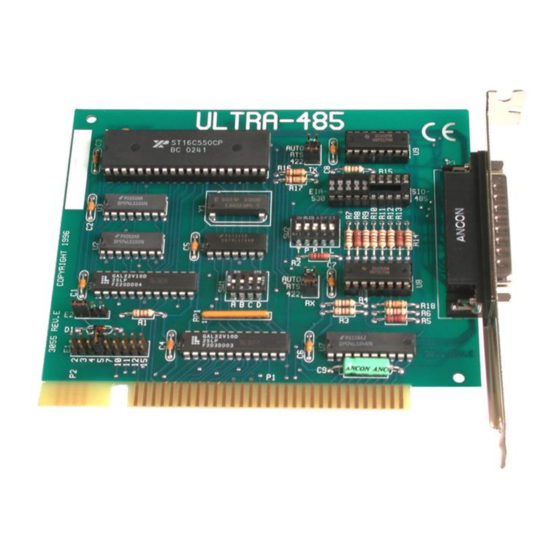
Page 23: Appendixe - Silk -Screen
Appendix E - Silk-Screen Appendix E - Silk-Screen Sealevel Systems ULTRA-485 Page 19... -
Page 24: Appendixf - Compliance Notices
Always use cabling provided with this product if possible. If no cable is provided or if an alternate cable is required, use high quality shielded cabling to maintain compliance wi th FCC/EMC directives. Sealevel Systems ULTRA-485 Page 20... -
Page 25: Warranty
Sealevel Systems, Inc. provides a lifetime warranty for this product. Should this product fail to be in good working order at any time during this period, Sealevel Systems will, at it's option, replace or repair it at no additional charge except as set forth in the following terms.
Need help?
Do you have a question about the ULTRA 485 and is the answer not in the manual?
Questions and answers