
Related Manuals for A/S WODSCHOW & CO AR30


Summary of Contents for A/S WODSCHOW & CO AR30
- Page 1 OPERATING INSTRUCTIONS AR30 AR40 / AR40P VL-1S AR60 / AR60P A/S Wodschow & Co. Kirkebjerg Søpark 6 Phone: +45 43 44 22 88 DK-2605 Brøndby info@wodschow.dk www.bearvarimixer.dk Denmark...
-
Page 2: Table Of Contents
ontents ....................................... 2 eneral ....................................... 2 afety : ..................................2 nstallatIon of new mIxer : .................................. 3 onstruCtIon of the mIxer : ................................... 3 he mIxers Control panel : ..............................4 he maxImum CapaCIty of the mIxer : ................................4 eCommended maxImum speeds : .................................. -
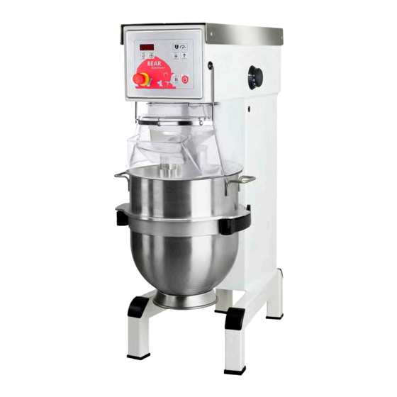
Page 3: C Onstruction Of The Mixer
Safety switch for safety guard Safety switch for lid (Optional) speed indicator Motor Size of Motor mixer AR30 1,0 kw AR40 1,1 kw AR40P 1,85 kw AR60 1,85 kw AR60P 3,0 kw Micro switch for the up-... -
Page 4: He Maximum Capacity Of The Mixer
CapaCIty of the mIxer Capacities per mix Tool AR30 AR40 AR40P AR60 AR60P 3,5 L Egg white Whip Whipped cream Whip 7,5 L 10 L 10 L 15 L 15 L Whip 24 L 32 L 32 L... -
Page 5: Owl Lifting And Speed Control
peratIon of the mIxer Speed indicator Place the tool in the bowl. Open the safety guard. Note: the bowl arms must be in the lowest position. Place the bowl in the bowl arms. Check that the ”Centre bowl is pushed right back into the arms and that the ear”... -
Page 6: Imer Function
Imer funCtIon tart up after stop at hIGh speed The mixer has an optional timer function. If no time is set If the emergency stop is activated or the safety guard on the timer, the display will instead show the time the has been opened while lifting or lowering the bowl... -
Page 7: Orrect Use Of Tools
orreCt use of tools until the grease gun feels hard to press or until grease comes out between the shaft and the pulleys. The meat mincer must not be used for production of bread crumbs as this will cause unnecessary The mixer must not be started until the screws wear and tear on some mixer parts. -
Page 8: Ist Of Errors And Djustment Of Special
Then follow the section: Start the mixer and leave it running while the nut (U) “Adjustment of speed” page 11 is tightened. Do not tighten it too much. AR30 292 mm +/- 3 mm. AR40/40P 292 mm +/- 3 mm. -
Page 9: A Djustment Of Bowl Centering
The distance (X) is measured from the bottom side of the bayonet hole to the surface on the bowl arms on which the bowl rests (fig. 6). The bowl arms must be lifted to normal working position. AR30 =162 mm. Bowl height (X): AR40 =162 mm. AR60 =178 mm fig.6... - Page 10 1 mm fig.7a Position of the the V-belt at minimum speed. 2-3 mm fig.8 ”Bad position” for the servo motor fig.7b Position of the the V-belt at maximum speed.
-
Page 11: A Djustments Of Speed ( Low And High Speed Cam Disks )
djustments of speed low and hIGh speed Cam dIsks Prior to any adjustment the, the bowl must be in its top position and the safety guard must be closed. Switch off the power to the mixer, this must be done via the emergency stop. Remove the lid of the mixer. Dismantle shaft for speed regulation: The arm (B) is released from the servo motor shaft by removing the cotter pin (C) and the pin (D). -
Page 12: E Lectrical Diagrams
leCtrICal dIaGrams Emergency stop Fuse 250V/1,5A Contactor Main Motor Thermal Relay Motor protection 230VAC/50Hz Hold Thermal Relay Supply Operator Panel Contactor Main Motor 3 x 200 - 240V AC + PE Power supply Max. 16A Main Motor Customer supplied Project title: Subject name: Project rev.: Page... - Page 13 L+ 24VDC -PCB Speed down 1 Servo Safety Operator minimum -CE1 micro(CE) panel micro Speed down 1 Safety guard safety micro -PCB Speed up 2 Operator panel Speed up 2 Servo maximum -PCB -PCB micro Start Stop Operator Operator panel panel Start Stop...
- Page 14 Emergency stop Fuse L1(N) 250V/1,5A Contactor Main Motor Thermal Relay Motor protection -PCB 230VAC/50Hz Hold Thermal Relay Supply Operator Panel Contactor Main Motor 3 x 200 - 240V AC + N + PE Main Motor 2 x 230V AC + PE Power supply Max.
- Page 15 L+ 24VDC -PCB Speed down 1 Servo Safety Operator minimum -CE1 micro(CE) panel micro Speed down 1 Safety guard safety micro -PCB Speed up 2 Operator panel Speed up 2 Servo maximum -PCB -PCB micro Start Stop Operator Operator panel panel Start Stop...
- Page 16 Emergency stop Fuse 250V/1,5A Contactor Main Motor Thermal Relay Motor protection 230VAC/50Hz Hold Thermal Relay Supply Operator Panel Contactor Main Motor 3 x 380 - 480V AC + N + PE Power supply Max. 16A Main Motor Customer supplied Project title: Subject name: Project rev.: Page...
- Page 17 L+ 24VDC -PCB Speed down 1 Safety Servo Operator -CE1 minimum micro(CE) panel micro Speed down 1 Safety guard safety micro -PCB Speed up 2 Operator panel Speed up 2 Servo maximum -PCB -PCB micro Start Stop Operator Operator panel panel Start Stop...
- Page 18 Emergency stop Fuse Transformer -TR1 250V/1,5A 400VAC 230VAC Contactor Main Motor Thermal Relay Motor protection 230VAC/50Hz Hold Thermal Relay Supply Operator Panel Contactor Main Motor 3 x 380 - 480V AC + PE Power supply Max. 16A Main Motor Customer supplied Project title: Subject name: Project rev.:...
- Page 19 L+ 24VDC -PCB Speed down 1 Safety Servo Operator minimum -CE1 micro(CE) panel micro Speed down 1 Safety guard safety micro -PCB Speed up 2 Operator panel Speed up 2 Servo maximum -PCB -PCB micro Start Stop Operator Operator panel panel Start Stop...
- Page 20 Indhold af Overensstemmelseserklæring, (Maskindirektivet, 2006/42/EC, Bilag II, del A) Contents of the Declaration of conformity for machinery, (Machinery Directive 2006/42/EC, Annex II., sub. A) Inhalt der Konformitätserklärung für Maschinen, (Richtlinie 2006/42/EG, Anhang II, sub A) Contenu de la Déclaration de conformité d’une machine, (Directive Machine 2006/42/CE, Annexe II.A) Inhoud van de verklaring van overeenstemming voor machines, (Richtlijn 2006/42/EC, Bijlage II, onder A) Contenido de la declaración de conformidad sobre máquinas, (Directiva 2006/42/EC, Anexo II, sub A) Fabrikant;...
- Page 21 Innehåll i örsäkran om maskinens överensstämmelse, (Maskindirektivet 2006/42/EG, bilaga 2, A) Contenuto della dichiarazione di conformità per macchine, (Direttiva 2006/42/CE, Allegato II, parte A) Sisukord masina vastavusdeklaratsioon , (Masinadirektiiv 2006/42/EÜ, lisa II, punkt A) Treść Deklaracja zgodności dla maszyn (Dyrektywa maszynowa 2006/42/WE, Załącznik II, pkt A) Sisältö...
- Page 24 A/S WODSCHOW & CO. Kirkebjerg Søpark 6 Phone: 43 44 22 88 DK-2605 Brøndby info@wodschow.dk Denmark www.bearvarimixer.com...
Need help?
Do you have a question about the AR30 and is the answer not in the manual?
Questions and answers