Table of Contents
Advertisement
Quick Links
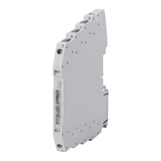
Ultra-slim Signal Converter
K3FP Series
Complete Lineup of Ultra-slim, High-
performance Converters for Every
Application
• Ultra-slim 6.2-mm size.
Close mounting makes devices more compact.
• Easily wired and flexible with 8 terminal blocks.
• Multi-range I/O provides flexibility for the desired signal format.
• High-precision analog conversion with minimum current
consumption.
• Reduced wiring through power supply connection with DIN rail
bus connector (optional).
Product Selection
Product
3-Way Signal Isolator
K3FP-YV-I-I
3-Way Signal Isolator
K3FP-YV-U-U
3-Way Signal Isolator
K3FP-VS-UI-UI
Dual Output 3-Way Signal
K3FP-VS-UI-2I
Isolator
Loop-powered Isolator
K3FP-SN1-I-I
(1-channel)
Loop-powered Isolator
K3FP-SN2-I-I
(2-channel)
Thermocouple Transducer
K3FP-TS-UI
RTD Transducer
K3FP-RS-UI
Repeater Power Supply
K3FP-DY-I-I
Limit Value Switch
K3FP-SL-UI
Model
Input signal
0 (4) to 20 mA DC
− 10 (0) to 10 V DC
0 to 20 mA DC, 4 to 20 mA DC,
0 to 10 V DC, 2 to 10 V DC,
0 to 5 V DC, 1 to 5 V DC
(selected by DIP switch setting)
0 to 20 mA DC, 4 to 20 mA DC,
0 to 10 V DC, 1 to 5 V DC
(selected by DIP switch setting)
0 (4) to 20 mA DC
0 (4) to 20 mA DC
Type J and K Thermocouples
(Conforms to IEC 60584-1)
(Input temperature range is
selected by DIP switch setting.)
PT100 Platinum Resistance
Thermometer
(Conforms to IEC 60751)
(Input temperature range is
selected by DIP switch setting.)
0 (4) to 20 mA DC
0 to 20 mA DC, 0 to 10 V DC
(selected by DIP switch setting)
Output signal
0 (4) to 20 mA DC
− 10 (0) to 10 V DC
0 to 20 mA DC, 4 to 20 mA DC,
0 to 10 V DC, 2 to 10 V DC,
0 to 5 V DC, 1 to 5 V DC
(selected by DIP switch setting)
0 to 20 mA DC, 4 to 20 mA DC
(selected by DIP switch setting)
0 (4) to 20 mA DC
0 (4) to 20 mA DC
0 to 20 mA DC, 4 to 20 mA DC,
20 to 0 mA DC, 20 to 4 mA DC,
0 to 5 V DC, 1 to 5 V DC,
0 to 10 V DC, 10 to 0 V DC
(selected by DIP switch setting)
0 to 20 mA DC, 4 to 20 mA DC,
20 to 0 mA DC, 20 to 4 mA DC,
0 to 5 V DC, 1 to 5 V DC,
0 to 10 V DC, 10 to 0 V DC
(selected by DIP switch setting)
0 (4) to 20 mA DC
SPDT output
Ultra-slim Signal Converter
Power supply
Reference
voltage
page
24 V DC
3
24 V DC
24 V DC
6
24 V DC
10
---
14
---
24 V DC
17
24 V DC
23
24 V DC
30
24 V DC
33
K3FP Series
1
Advertisement
Table of Contents

Subscribe to Our Youtube Channel
Related Manuals for Omron K3FP Series


Summary of Contents for Omron K3FP Series
- Page 1 Ultra-slim Signal Converter K3FP Series Complete Lineup of Ultra-slim, High- performance Converters for Every Application • Ultra-slim 6.2-mm size. Close mounting makes devices more compact. • Easily wired and flexible with 8 terminal blocks. • Multi-range I/O provides flexibility for the desired signal format.
- Page 2 K8AB-VS/K8AB-VW DIP switch) For AC voltage three-phase signal inputs: K8AB-PW For thermocouple and platinum resistance Data Logger thermometer sensor inputs: K8AB-TH For details, refer to Measuring and Monitoring Relays K8AB Series/ 61F-D21T (Cat. No.: N141). K3FP Series Ultra-slim Signal Converter...
-
Page 3: Ordering Information
3-Way Signal Isolator K3FP-YV-I-I/K3FP-YV-U-U 6.2-mm Ultra-slim Isolator • Isolates between input, output, and power supply. 1,500 V AC dielectric strength. • Close mounting. • CE Marking compliant. • UL certified. Refer to Common Precautions on page 38. Ordering Information K3FP-YV-I-I K3FP-YV-U-U ■... - Page 4 ■ Input Specifications Item Model K3FP-YV-I-I K3FP-YV-U-U Ambient storage 95% max. (with no condensation) − 10 (0) to 10 V DC Input signal 0 (4) to 20 mA DC humidity Item Connection method Screw connections (M3) Approx. 50 Ω Approx. 100 k Ω Input impedance Tightening torque 0.5 N·m...
- Page 5 Connections ■ Internal Block Diagram Input signal Output signal − − Supply voltage Supply voltage − − K3FP-1 Dimensions Note: All units are in millimeters unless otherwise indicated. Note: 1. Use solid wire with a diameter K3FP-YV-I-I of 2.5 mm max.
- Page 6 3-Way Signal Isolator K3FP-VS-UI-UI 6.2-mm Ultra-slim Isolator with 36 Input and Output Combinations. • Input and output ranges can be easily changed using an external DIP switch. • Isolates between input, output, and power supply. 1,500 V AC dielectric strength. •...
- Page 7 ■ Input Specifications Connecting Solid 0.14 to 2.5 mm cable wire Input signal 0 to 20 mA DC, 0 to 10 V DC, Stranded 0.2 to 2.5 mm 4 to 20 mA DC 2 to 10 V DC, wire 0 to 5 V DC, 24 to 12 Item 1 to 5 V DC...
-
Page 8: Dip Switch Settings
DIP Switch Settings All DIP switches are turned OFF at shipment. Set input and output signals using DIP switches S1 and S2. SWITCH DIP switch S2 DIP switch S1 ON ● ↑ OFF ❍ ↓ Input signal Output signal ❍ ❍... - Page 9 Connections ■ Internal Block Diagram Input signal Output signal − − Supply voltage Supply voltage − − K3FP-1 Dimensions Note: All units are in millimeters unless otherwise indicated. Note: 1. Use solid wire with a diameter K3FP-VS-UI-UI of 2.5 mm max.
- Page 10 Dual Output 3-Way Signal Isolator K3FP-VS-UI-2I 6.2-mm Ultra-slim Dual Output 3-Way Signal Isolator • Outputs two isolated signals. • Isolated between input, output 1, output 2, and between power supply. 1,500 V AC dielectric strength. • Close mounting. • CE Marking compliant. •...
- Page 11 ■ Input Specifications Connecting Solid 0.14 to 2.5 mm cable wire Input signal 0 to 20 mA DC, 0 to 10 V DC, Stranded 0.2 to 2.5 mm Item 4 to 20 mA DC 1 to 5 V DC wire Approx.
-
Page 12: Analog Output Operation
DIP Switch Settings Analog Output Operation All DIP switches are turned OFF at shipment. DIP switch S1 is used Setting Example for 1 to 5-V Input and 4 to 20-mA Output: to select input and output signals and analog output limit operation. Output: 4 to 20 mA (mA) SWITCH... - Page 13 Dimensions Note: All units are in millimeters unless otherwise indicated. Note: 1. Use solid wire with a diameter K3FP-VS-UI-2I of 2.5 mm max. or bar terminals with insulation 93.1 sleeves for terminal connections. To preserve dielectric strength after connection, the length of the exposed conductive part inserted into the terminal must be 12 mm max.
- Page 14 Loop-powered Isolator K3FP-SN1-I-I/K3FP-SN2-I-I 6.2-mm Ultra-slim Loop-powered Isolator • Draws the power required to drive the amplifier from the input current signal. • Isolated between input and output. 1,500 V AC dielectric strength. • Close mounting. • CE Marking compliant. • UL certified. Refer to Common Precautions on page Ordering Information Ratings and Specifications...
- Page 15 ■ Input Specifications Item Model K3FP-SN1-I-I K3FP-SN2-I-I Connecting Solid 0.14 to 2.5 mm Item Input signal 0 to 20 mA DC, 4 to 20 mA DC cable wire Input impedance Changes depending on the load on the Stranded 0.2 to 2.5 mm output side.
-
Page 16: Operation
Dimensions Note: All units are in millimeters unless otherwise indicated. Note: 1. Use solid wire with a diameter K3FP-SN1-I-I of 2.5 mm max. or bar K3FP-SN2-I-I terminals with insulation 93.1 sleeves for terminal connections. To preserve dielectric strength after connection, the length of the exposed conductive part inserted into the terminal must be 12 mm max. - Page 17 Thermocouple Transducer K3FP-TS-UI 6.2-mm Ultra-slim Thermocouple Transducer • Converts measured values for type J and K thermocouple sensors into analog signals. • Measurement range can be set between −150 and 1,350°C. • Isolates between input, output, and power supply. 1,500 V AC dielectric strength.
- Page 18 ■ Input Specifications Connecting Solid 0.14 to 2.5 mm cable wire Input signal Type J and K Thermocouples Stranded 0.2 to 2.5 mm Item (Conforms to IEC 60584-1) wire Measurement range J: − 150 to 1,200 ° C 24 to 12 K: −...
- Page 19 DIP Switch Settings All DIP switches are turned OFF at shipment. DIP Switch S1 DIP Switch S3 DIP switch S1 is used to set the thermocouple type, cold junction DIP switch S3 is used to select the current output and voltage output compensation enable/disable, output signal range, and the start of for output signals.
- Page 20 DIP Switch S2 DIP switch S2 is used to select the measurement range end value and output status for errors. SWITCH DIP switch S2 SWITCH DIP switch S2 ON ● ↑ ON ● ↑ OFF ❍ ↓ OFF ❍ ↓ End temperature End temperature [ °...
- Page 21 Output Status for Errors SWITCH DIP switch S2 ON ● ↑ OFF ❍ ↓ Output status When disconnected on Above measurement range Below measurement range for errors thermocouple side ❍ ❍ Held at 5% of maximum rated Held at 2.5% of maximum rated Held at minimum rated output.
- Page 22 Connections ■ Internal Block Diagram Output signal − Supply voltage − K3FP-1 Dimensions Note: All units are in millimeters unless otherwise indicated. Note: 1. Use solid wire with a diameter K3FP-TS-UI of 2.5 mm max. or bar terminals with insulation 93.1 sleeves for terminal connections.
- Page 23 RTD Transducer K3FP-RS-UI 6.2-mm Ultra-slim RTD Transducer • Converts measured values from PT100 platinum resistance thermometers into analog signals. • A 2-conductor, 3-conductor, or 4-conductor PT100 platinum resistance thermometer can be connected to the input terminal. • Measurement range can be set between −150 and 850 °...
- Page 24 ■ Input Specifications Connecting Solid 0.14 to 2.5 mm cable wire Input signal PT100 platinum resistance thermometer Stranded 0.2 to 2.5 mm Item (conforms to IEC 60751) wire Measurement range − 150 to 850 ° C 24 to 12 Min. 50 ° C Min.
- Page 25 DIP Switch Settings All DIP switches are turned OFF at shipment. DIP Switch S1 DIP Switch S3 DIP switch S1 is used to set the connection method, output signal DIP switch S3 is used to select current and voltage outputs for output range, and measurement range start value.
- Page 26 DIP Switch S2 DIP switch S2 is used to select the measurement range end value and output status for errors. SWITCH DIP Switch S2 SWITCH DIP Switch S2 ON ● ↑ ON ● ↑ OFF ❍ ↓ OFF ❍ ↓ End temperature End temperature [ °...
- Page 27 Output Status for Errors SWITCH DIP switch S2 ON ● ↑ OFF ❍ ↓ Output status When disconnected on Above measurement Below measurement When short-circuited on for errors platinum resistance range range platinum resistance thermometer side thermometer side ❍ ❍ Held at 5% of maximum Held at 2.5% of maximum Held at minimum rated...
- Page 28 Output Signal Range 1 to 5 V Output status DIP switch S2 When disconnected on Above measurement Below measurement When short-circuited on for errors platinum resistance range range platinum resistance thermometer side thermometer side ❍ ❍ 5.25 V 5.125 V ●...
- Page 29 Precautions Refer to pages 38 and 39 for common precautions. ■ Precautions for Correct Use Diagnostics Indicator 4-conductor Connections • For long distances between the PT100 platinum resistance The diagnostics indicator (LED) inside the translucent cover shows thermometer and the K3FP-RS-UI and different cable resistances the error status, as outlined in the following table.
- Page 30 Repeater Power Supply K3FP-DY-I-I 6.2-mm Ultra-slim Repeater Power Supply • Isolates between input, output, and power supply. 1,500 V AC dielectric strength. • Close mounting. • CE Marking compliant. • UL certified. Refer to Common Precautions on page Ordering Information Ratings and Specifications ■...
- Page 31 ■ Input Specifications Housing material Weight 55 g Input signal 0 to 20 mA DC, 4 to 20 mA DC Safety standards UL 508 Item EMI: Approx. 50 Ω Input impedance Radiated EMI: EN 55011 Max. input signal 50 mA EMS: Transmitter supply Power supply voltage: 4.5 V max.
- Page 32 Dimensions Note: All units are in millimeters unless otherwise indicated. Note: 1. Use solid wire with a diameter K3FP-DY-I-I of 2.5 mm max. or bar terminals with insulation 93.1 sleeves for terminal connections. To preserve dielectric strength after connection, the length of the exposed conductive part inserted into the terminal must be 12 mm max.
-
Page 33: Limit Value Switch
Limit Value Switch K3FP-SL-UI 6.2-mm Ultra-slim Limit Value Switch • Accurate setting of comparative judgment values using the Unit's potentiometer. • Isolates between input, output, and power supply. 1,500 V AC dielectric strength. • Close mounting. • CE Marking compliant. •... - Page 34 ■ Output Specifications Safety standards UL 508 EMI: Output signal SPDT Radiated EMI: EN 55011 Item EMS: Contact output Yellow indicator (LED) ESD immunity: EN 61000-4-2 status display Rated electromagnetic field immunity: Applicable load 250 V AC, 2 A EN 61000-4-3 Contact material AgSnO Burst immunity:...
- Page 35 DIP Switch Settings All DIP switches are turned OFF at shipment. DIP Switch 1 DIP switch S1 is used to set the input signal range, hysteresis, contact operation (delay time), and contact drive method. SWITCH DIP switch S1 ON ● ↑ OFF ❍...
- Page 36 Dimensions Note: All units are in millimeters unless otherwise indicated. Note: 1. Use solid wire with a diameter K3FP-SL-UI of 2.5 mm max. or bar terminals with insulation 93.1 sleeves for terminal connections. To preserve dielectric strength after connection, the length of the exposed conductive part inserted into the terminal must be 12 mm max.
-
Page 37: Output Operation
Precautions Refer to pages 38 and 39 for common precautions. ■ Precautions for Correct Use Indicators Output Operation The status indicator (yellow LED) inside the translucent cover shows Terminals 3 and 4 are closed and terminals 2 and 3 are open when when voltage is applied to the contact coil, i.e., that the contact is the Unit power is OFF. - Page 38 Common Precautions Refer to Precautions in each product information sheet for specific 5. Do not use organic solvents (e.g., thinners or benzene), strong precautions for individual products. alkaline, or strong acidic material on the outside of the product. Doing so will damage the outer cover of the product. !CAUTION 6.
-
Page 39: Power Supply Voltage
Mounting Mounting the K3FP • The K3FP can be mounted on to all 35-mm DIN rail corresponding to EN 60715. When connecting the K3FP to a DIN rail bus connector, take particular care with the direction of both the K3FP and the Power Bridge. - Page 40 Warranty and Limitations of Liability WARRANTY OMRON's exclusive warranty is that the products are free from defects in materials and workmanship for a period of one year (or other period if specified) from date of sale by OMRON. OMRON MAKES NO WARRANTY OR REPRESENTATION, EXPRESS OR IMPLIED, REGARDING NON-INFRINGEMENT, MERCHANTABILITY, OR FITNESS FOR PARTICULAR PURPOSE OF THE PRODUCTS.
- Page 41 Mouser Electronics Authorized Distributor Click to View Pricing, Inventory, Delivery & Lifecycle Information: Omron K3FP-YV-U-U...
Need help?
Do you have a question about the K3FP Series and is the answer not in the manual?
Questions and answers