
Related Manuals for ARMTEL ACM-IP2.1


Summary of Contents for ARMTEL ACM-IP2.1
- Page 1 ACM-IP2.1 Analogue subsystems module RMLT.465275.015UM User Manual Document version 26.30.2 2021...
- Page 2 © Armtel info@armtel.com...
-
Page 3: Introduction
Short name of the product is ACM-IP2.1. ACM-IP2.1 is used at the enterprises of metallurgical, chemical, mining, gas and oil producing, metal-working and wood-working industry, and at facilities of the Russian Traffic Ministry, the Ministry of Emergency Situations, the Ministry of Internal Affairs and the Ministry of Defense, etc. -
Page 4: Safety Provisions
ANALOGUE SUBSYSTEMS MODULE User Manual SAFETY PROVISIONS During installation and operation of ACM-IP2.1, observe safety precautions laid out in local regulations on electrical safety. In order to ensure fire safety, observe the following rules: − before connecting the product to the power supply, make sure the power and communication cables are properly insulated;... -
Page 5: Table Of Contents
3.4 Checking operability ............................24 4 REPAIR… ..................................... 25 5 STORAGE .................................... 25 6 TRANSPORTATION ................................. 25 7 DISPOSAL ................................... 25 APPENDIX А (reference) ACM-IP2.1 connection ....................26 APPENDIX B (reference) Examples of ACM-IP2.1 connection ................28 armtel.com стр. 3/32 info@armtel.com © Armtel... -
Page 6: Description And Operation
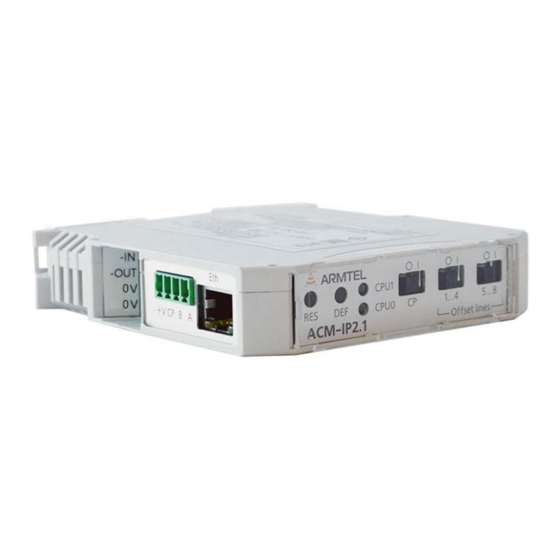
ACM-IP2.1 is installed on the DIN-rail 35 mm wide in communication cabinets, racks located in offices and control rooms. АСМ-IP2.1 appearance is shown in Figure 2. - Page 7 ANALOGUE SUBSYSTEMS MODULE User Manual Figure 1 — Example of ACM-IP2.1 operation within distributed intercom and alarm systems For example, organization of simplex communication sessions on routes: – DIS-IP2 — Ethernet interface — Fast Ethernet Switch — Ethernet interface — ACM- IP2.1 module —...
-
Page 8: Main Specifications
ACM-IP2.1 ANALOGUE SUBSYSTEMS MODULE User Manual 1.2 Main specifications Main specifications of ACM-IP2.1 are given in Table 1. Table 1 — Main specifications Parameter Value Main specifications of ACM-IP2.1 Rated power supply voltage Permissible supply voltage range from 36 to 60 Conformity with the PoE class IEEE 802.3af Class 0... -
Page 9: Operating Conditions
32 kHz (in the local memory) under SIP protocol and when using SIP-codec G.722.1С. When using Armtel-IP protocol, the bandwidth is 300 to 6800 kHz. Maximum permitted total output current of control lines when supplied from PoE Class 0 source (injector), max., А: 0.22. -
Page 10: Scope Of Supply
ACM-IP2.1 ANALOGUE SUBSYSTEMS MODULE User Manual 1.4 Scope of supply The scope of supply for ACM-IP2.1 is provided in Table 3. Table 3 — Scope of supply Quantity Identification Name Note [pcs] ACM-IP2.1 Analogue subsystems RMLT.465275.015 module Additional info on scope of supply... -
Page 11: Design
(see Figure 2) intended to secure a standard DIN-rail 35 mm. ACM-IP2.1 weight does not exceed 0,2 kg. External appearance and overall dimensions are given at Figure 2. line connector (connection of 1-8 control lines); 2 transparent flap cover;... - Page 12 14 – connector for connection of external DC power supply 48 W. In case of no PoE, it is used as an input for power supply connection. When ACM-IP2.1 is supplied from PoE, it is used as an output for supplying external devices connected to this ACM-IP2.1 (for example, an analog intercom).
- Page 13 ACM-IP2.1 reboots. 11 – RES reset button. To reset ACM-IP2.1, shortly press and depress the button, and wait until rebooting. Figure 2 does not show the following elements within the housing of ACM-IP2.1: −...
- Page 14 − X2 — not used in this version of the device; − XP1 — UART process connector (TTL level 3.3 V). Each ACM-IP2.1 contains firmware and factory settings (IP address and MAC address). To provide communication, IP network built using standard network equipment is needed.
-
Page 15: Labeling
ACM-IP2.1 ANALOGUE SUBSYSTEMS MODULE User Manual 1.6 Labeling A bilingual nameplate is attached to the ACM-IP2.1 housing (in Russian and English) made by laser printing. The nameplate contains the following information: name, trademark and reference information of the manufacturer; −... -
Page 16: Package
User Manual 1.7 Package ACM-IP2.1 with the products and documents, which come with the supply package, is packed in an individual container (a cardboard box) according to GOST 23088-80. A label in Russian language and English language is glued onto the consumer package, said label containing the following inscriptions and symbols: −... -
Page 17: Intended Use
1000 V, comply with the safety precautions stated in Occupational Safety Rules When Operating Electrical Installations. 2.1.2 ACM-IP2.1 can be powered from PoE injector and 48 VDC external power supply 15 W min. 2.1.3 The requirements for operating conditions and the place of installation given in this document take into account the most typical factors that affect the operation of the device. -
Page 18: Preparation For Use
− protect power and communication cables from damage. 2.3 Preparation for use Preparation of the ACM-IP2.1 for use shall be carried out by the manufacturer’s representatives, or personnel trained to operate Armtel LLC products. The main preparation of the product for use is carried out during installation and connection. -
Page 19: Installation, Connection, And Dismantling
To attach ACM-IP2.1 at the workplace, the housing has a latch to secure to DIN-rail 35 mm. The unit is attached as per Figure 3: − place ACM-IP2.1 above a DIN-rail 35 mm and engage the upper part of the DIN- rail with the upper groove of the device (a);... -
Page 20: Connection
Terminal devices are connected on the other side of the cable. 2.4.2.4 The availability of reverse polarity protection at the ACM-IP2.1 input prevents damage to the device, and so the performance of the device is not affected when reverse polarity supply voltage is applied across contacts 1, 3 and 4 of -IN –OUT 0 V 0 V connector. -
Page 21: Dismantling
ANALOGUE SUBSYSTEMS MODULE User Manual 2.4.3 Dismantling ACM-IP2.1 is dismantled in the following order: − power off the device; − remove the device from the DIN-rail as per Figure 4: 1) use a screwdriver suitable in size to loosen the fixing spring on the attachment latch (a);... -
Page 22: Operation
WEB interface, which can also be used for updating software, downloading and storing configurations. When ACM-IP2.1 is powered via PoE line, orange LED on Eth connector is ON, which indicates normal operation of the unit. To turn off ACM-IP2.1, you should disconnect the interface cable from Eth connector. -
Page 23: Troubleshooting
Possible cause Solution Check reliability of cable connections, ensure that the No power on connected power from ACM-IP2.1 to the analogue subscriber unit The subscriber is unable to subscriber units is supplied and make or receive calls connection is correct... - Page 24 Loud-speaking system does devices not transmit messages Contact the manufacturer for ACM-IP2.1 faulty diagnostics and repair * ACM-IP2.1 connections and functions are configured using IPN Config Tool software or a built-in WEB interface стр. 22/32 armtel.com © Armtel info@armtel.com...
-
Page 25: Maintenance
− visual inspection of the ACM-IP2.1 housing for mechanical damage (cracks, dents, etc.) on the enclosure, buttons and switches; − visual inspection of cables coming to ACM-IP2.1. They must not be crimped, have bending (bending radius must be at least five cable diameters) or have damages of outer sheath;... -
Page 26: Checking Operability
GOST R 2.610-2019 Unified system for design documentation. Guidelines for Preparation of Operating Documents, for form filling. 3.4 Checking operability The efficiency of ACM-IP2.1 should be tested with equipment connected devices to it. (Appendix B). Verify ACM-IP2.1 with an analog call station: −... -
Page 27: Repair
− the shipping container on the shipping vehicle is fastened to avoid falling and collision.. ote — ACM-IP2.1 transportation is allowed as part of a cabinet (rack), in which equipment designed for installation in a cabinet is installed. АСМ-IP2.1 must be latched to the DIN-rail. -
Page 28: Appendix А (Reference) Acm-Ip2.1 Connection
User Manual APPENDIX А (REFERENCE) ACM-IP2.1 CONNECTION The pin numbers and the designation of the circuits for external connection is given in Table А.1. Location of connectors in the unit is given in Figure 1. Table A.1 - The pin numbers and the designation of the circuits for external connection... - Page 29 ACM-IP2.1 ANALOGUE SUBSYSTEMS MODULE User Manual Table A.1- The pin numbers and the designation of the circuits for external connection (end) Contact Connector Identification Function -48 V. Power input when externally supplied -OUT -48 V. Output when powered over РоЕ...
-
Page 30: Appendix B (Reference) Examples Of Acm-Ip2.1 Connection
(REFERENCE) EXAMPLES OF ACM-IP2.1 CONNECTION 1 An example of connection of analog intercom to ACM-IP2.1 is shown in Figure B.1. Figure B.1 — Connection of analog intercom Similar to the intercom keys, the outputs of the "dry contact" relay from external automation and alarm systems can be connected to ACM-IP2.1. - Page 31 User Manual 2 An example for construction of zonal loud-speaking alarm system with the help of ACM-IP2.1 (up to eight zones) is illustrated at Figure B.2. Figure B.2 — Construction of zonal loud-speaking alarm system Note – This diagram is an example for construction of a zonal alarm system, but other switching options are possible, both for loudspeakers and for the input of power amplifier.
- Page 32 ANALOGUE SUBSYSTEMS MODULE User Manual 3 An example for construction an interaction scheme with automation and alarm devices ("dry contacts") to ACM-IP2.1 is shown in Figure B.3. Figure B.3 — Interaction scheme with automation and alarm devices ("dry contacts") стр. 30/32 armtel.com...
- Page 33 ACM-IP2.1 ANALOGUE SUBSYSTEMS MODULE User Manual NOTES armtel.com стр. 31/32 info@armtel.com © Armtel...
- Page 34 ACM-IP2.1 ANALOGUE SUBSYSTEMS MODULE User Manual стр. 32/32 armtel.com © Armtel info@armtel.com...
- Page 35 © Armtel...
- Page 36 ARMTEL LLC Tel./fax: +7 (812) 703-41-11 www.armtel.com | info@armtel.com Legal and physical address: Russia, 192012, Saint Petersburg, Zaporozhskaya str., 12 building 1, office 1/2 TECHNICAL SUPPORT 8-800-500-90-17 (for calls from Russian Federation) +7-812-633-04-02 (for international calls) support@armtel.com MORE INFORMATION ABOUT PRODUCT ON OFFICIAL SITE...
Need help?
Do you have a question about the ACM-IP2.1 and is the answer not in the manual?
Questions and answers