
Related Manuals for ARMTEL ACM-IP2


Summary of Contents for ARMTEL ACM-IP2
- Page 1 ACM-IP2 Analogue subsystems module RMLT.465275.006UM User Manual Document version 12 26.30.11.190 2020...
- Page 2 © Armtel info@armtel.com...
-
Page 3: Introduction
ACM-IP2 ANALOGUE SUBSYSTEMS MODULE User Manual INTRODUCTION This User Manual is intended for introducing ACM-IP2 Analogue subsystems module RMLT.465275.006 manufactured by Armtel LLC, Russia to the User. ACM-IP2 Analogue subsystems module provides the functions of bi-directional conversion of the digital IP-interface to analog for providing Public Address/ General Alarm... -
Page 4: Safety Provisions
ACM-IP2 ANALOGUE SUBSYSTEMS MODULE User Manual SAFETY PROVISIONS During installation and operation of ACM-IP2, observe safety precautions laid out in local regulations on electrical safety. In order to ensure fire safety, follow the following rules: − before connecting the product to the power supply, make sure the power and communication cables are properly insulated;... -
Page 5: Table Of Contents
3.4 Checking operability ............................19 4 REPAIR ....................................20 5 STORAGE .................................... 20 6 TRANSPORTATION ................................. 21 7 DISPOSAL ................................... 21 APPENDIX A (reference) ACM-IP2 Connection diagrams ................... 22 APPENDIX B (reference) ACM-IP2 External appearance ..................26 armtel.com page 3/28 info@armtel.com... -
Page 6: Description And Operation
User Manual 1 DESCRIPTION AND OPERATION 1.1 Features ACM-IP2 is designed for use in distributed and centralized digital Intercom and Public Address / General Alarm communication systems (based on allotted SIP server) at industrial and transportation facilities. АСМ-IP2 enables to use analogue equipment and to interact with automation and alarm units. - Page 7 ACM-IP2 ANALOGUE SUBSYSTEMS MODULE User Manual Configuration of АСМ-IP2 is performed from the administrator's PC, on which the "IPN2 Configuration Software" RU.RMLT.00041-01 should be installed. Figure 1 shows several alternatives of АСМ-IP2 usage. Figure 1 – Example of АСМ-IP2 operation within distributed intercom and alarm systems For example, organization of simplex communication sessions on routes: - DIS-IP2 –...
-
Page 8: Main Specifications
ACM-IP2 ANALOGUE SUBSYSTEMS MODULE User Manual 1.2 Main specifications Main specifications and operational characteristics of ACM-IP2 are given in the Table 2. Table 2 – Main specifications and operational characteristics Parameter Value Main specifications of ACM-IP2 Power supply by PoE plus line (IEEE 802.3at), V... - Page 9 ACM-IP2 ANALOGUE SUBSYSTEMS MODULE User Manual Table 2 – Main specifications and operational characteristics (end) Parameter Value Parameters of built-in amplifier Number of channels of the built-in amplifier, pcs. 2*** Power of integrated amplifier per one channel (at 8 Ohm load), min, W Parameters of control lines Number of control lines (programmable), pcs.
-
Page 10: Scope Of Supply
ACM-IP2 ANALOGUE SUBSYSTEMS MODULE User Manual 1.3 Scope of supply The scope of supply for ACM-IP2 is provided in Table 3. Table 3 – Scope of supply Quanti- Identification Name Note ty, pcs. RMLT.465275.006* ACM-IP2 Analogue subsystems module Product components RMLT.468158.001... -
Page 11: Design
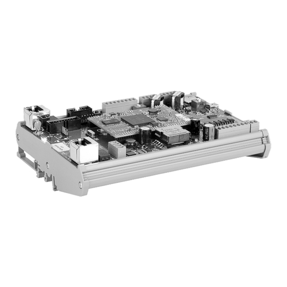
ACM-IP2 ANALOGUE SUBSYSTEMS MODULE User Manual 1.4 Design ACM-IP2 is a printed board with electronic components, inserted in casing and fixed on DIN-rail 35 mm wide. ACM-IP2 external appearance and overall dimensions are given at Figure 2. a) elements view b) bottom view Figure 2 –... - Page 12 − Х22 – negative potential on the load line, for example, the relay windings; − Х42 – micro-SD card slot with card installed. Each ACM-IP2 contains firmware and factory settings (IP address and MAC address). To provide communication, IP network built using standard network equipment is needed.
-
Page 13: Adsl-Ip2 Adapter
The operating mode for ADSL-IP2 Adapter (ADSL or Wi-Fi) is set by software during configuration of ACM-IP2. Communication with the ADSL-IP2 Adapter is executed by IP-address, while the input signal via USB-interface is transmitted to ACM-IP2, thus providing communication with the terminal analog units. - Page 14 ACM-IP2 ANALOGUE SUBSYSTEMS MODULE User Manual When working on a wireless data link, Wi-Fi adapter supports IEEE 802.11a/b/g/n protocol to operate at 2.4 GHz with a bandwidth of up to 20 MHz. The speed of data transfer using Wi-Fi technology reaches 300 Mbit / s. The adapter uses all-directional Wi-Fi antenna...
-
Page 15: Labeling
The serial number is unique for each product. 1.7 Package ACM-IP2 with the assembly kit and documents, which come with the supply package, is packed in consumer package (cardboard box). A label in Russian language and English language is glued onto the consumer package, said label containing the following inscriptions and symbols: −... -
Page 16: Intended Use
48 V supply from a DC power source with a power of at least 30 W to contacts 2, 3 of the socket X21 of the ACM-IP2. The connection should be carried out with a 2-core cable with a cross section of at least 0.35mm 2.1.3 When installing ACM-IP2 (version RMLT.465275.006-01) together with the... -
Page 17: Preparation For Use
− inspect ACM-IP2 enclosure visually, no mechanical damages (cracks, dents, etc.) on the enclosure, board and elements are allowed; − install ACM-IP2 at the operation site (click on the DIN-rail). The location in the cabinet should be chosen taking into account the convenience of access to the module for connecting the power and communication wires, as well as for maintenance. - Page 18 ACM-IP2 before being connected to the network. To this end, you can use direct connection of ACM-IP2 to the service computer. In this case, to power ACM-IP2, you should use PoE injector or supply -48 V to "X21"...
-
Page 19: Operation
"IPN2 Configuration Software" RU.RMLT.00041-01 should be installed. When ACM-IP2 is powered via PoE plus line, orange LED on X1 (or X2) socket is ON, which indicates normal operation of the unit. To turn off ACM-IP2, you should disconnect the interface cable from socket X1 (or X2). - Page 20 ACM-IP2 ANALOGUE SUBSYSTEMS MODULE User Manual 2.4.3 Safety precautions To avoid electric shock, do not operate the product with a damaged power or communication cable. ATTENTION! NEVER DISMANTLE THE PRODUCT CONNECTED TO MAINS OR EXTERNAL POWER SUPPLY. Do not use the product in rooms with high humidity (more than 80 %) or conductive dust.
-
Page 21: Maintenance
3.3 Maintenance procedure Maintenance includes as follows: − during installation of ACM-IP2 in the cabinet, it is necessary to open the cabinet, make sure that there is no moisture inside, make a visual inspection of the ACM-IP2, if necessary, clean the terminal blocks and the unit from dust with an air jet. -
Page 22: Repair
ACM-IP2 ANALOGUE SUBSYSTEMS MODULE User Manual 4 REPAIR Scheduled repairs of the product are not provided for. Unscheduled repair shall be performed by the manufacturer at the request of the user. The location, time, procedure and cost of the work shall be agreed on in advance. -
Page 23: Transportation
− the shipping container on the shipping vehicle is fastened to avoid falling and collision. Note – ACM-IP2 transportation is allowed as part of a cabinet (rack), in which equipment designed for installation in a cabinet is installed. ACM-IP2 and ADSL-IP2 Adapter (if any) must be snapped onto a DIN-rail. -
Page 24: Appendix A (Reference) Acm-Ip2 Connection Diagrams
ACM-IP2 ANALOGUE SUBSYSTEMS MODULE User Manual APPENDIX A (REFERENCE) ACM-IP2 CONNECTION DIAGRAMS The pin numbers and the designation of the circuits for external connection is given in Table А.1. The numbering of contacts and the designation of circuits on the module are in accordance with Figure 2. - Page 25 ACM-IP2 ANALOGUE SUBSYSTEMS MODULE User Manual 1 An example of connection of AW type analogue call station manufactured by Armtel to ACM-IP2 is shown in Figure A.1. Figure A.1 – Connection of analogue call station Similar to the call station keys, the outputs of the "dry contact" relay from external automation and alarm systems can be connected to ACM-IP2.
- Page 26 ACM-IP2 ANALOGUE SUBSYSTEMS MODULE User Manual 3 Designation od outputs of 100BaseT Ethernet RJ-45 socket of ACM-IP2 is given in Table А.2. Table A.2 - Designation od outputs of 100BaseT Ethernet RJ-45 socket Pin No Designation Data transfer (TX+) Data transfer (TX-)
- Page 27 ACM-IP2 ANALOGUE SUBSYSTEMS MODULE User Manual 4 Designation of outputs of RJ-12 6Р6С socket of ADSL-IP2 Adapter is illustrated in Table А.3. Table A.3 - Designation of outputs of RJ-12 6Р6С socket Pin No Designation no connected no connected ADSL_TIP...
-
Page 28: Appendix B (Reference) Acm-Ip2 External Appearance
ACM-IP2 ANALOGUE SUBSYSTEMS MODULE User Manual APPENDIX B (REFERENCE) ACM-IP2 EXTERNAL APPEARANCE Figure B.1 – External appearance of variant ACM-IP2 RMLT.465275.001 Figure B.2 – External appearance of variant ACM-IP2 RMLT.465275.001-01 page 26/28 armtel.com © Armtel info@armtel.com... - Page 29 ACM-IP2 ANALOGUE SUBSYSTEMS MODULE User Manual NOTES armtel.com page 27/28 info@armtel.com © Armtel...
- Page 30 ACM-IP2 ANALOGUE SUBSYSTEMS MODULE User Manual page 28/28 armtel.com © Armtel info@armtel.com...
- Page 31 © Armtel...
- Page 32 ARMTEL LLC Tel./fax: +7 (812) 703-41-11 www.armtel.com | info@armtel.com Legal and physical address: Russia, 192012, Saint Petersburg, Zaporozhskaya str., 12 building 1, office 1/2 TECHNICAL SUPPORT 8-800-500-90-17 (for calls from Russian Federation) +7-812-633-04-02 (for international calls) support@armtel.com MORE INFORMATION ABOUT PRODUCT ON OFFICIAL SITE...
Need help?
Do you have a question about the ACM-IP2 and is the answer not in the manual?
Questions and answers