Table of Contents
Advertisement
Quick Links
Advertisement
Table of Contents

Related Manuals for Advantech AIR-101


Summary of Contents for Advantech AIR-101
- Page 1 User Manual AIR-101 Fanless AI Inference System...
- Page 2 This product contains a hard copy of the Chinese user manual for China CCC certification purposes. A PDF of the English user manual is included on the accompanying CD. Please disregard the hard copy Chinese user manual if the product is not sold and/or installed in China. AIR-101 User Manual...
- Page 3 The documentation and the software included with this product are copyrighted 2020 by Advantech Co., Ltd. All rights are reserved. Advantech Co., Ltd. reserves the right to improve the products described in this manual at any time without notice. No part of this manual may be reproduced, copied, translated, or transmitted in any form or by any means without the prior written permission of Advantech Co., Ltd.
- Page 4 Product Warranty (2 Years) Advantech warrants the original purchaser that all of its products will be free from defects in materials and workmanship for two years from the date of purchase. This warranty does not apply to any products that have been repaired or altered by persons other than repair personnel authorized by Advantech, or products that have been subject to misuse, abuse, accident, or improper installation.
- Page 5 Technical Support and Assistance Visit the Advantech website at www.advantech.com/support to obtain the latest product information. Contact your distributor, sales representative, or Advantech's customer service center for technical support if you need additional assistance. Please have the following information ready before calling: –...
- Page 6 70 dB (A). The equipment should only be installed in a restricted access area. DISCLAIMER: These instructions are provided according to IEC 704-1 specifi- cations. Advantech disclaims all responsibility for the accuracy of any state- ments contained herein. AIR-101 User Manual...
- Page 7 FSP/ FSP060-DAAN2) suitable for use at TMA 60 °C (140 °F) min., and the out- put is rated 24 V , 2.5A min., ES1. If you need further assistance, contact Advantech for additional information. Consignes de Sécurité Veuillez lire attentivement ces instructions de sécurité.
- Page 8 L'équipement ne doit être installé que dans une zone d'accès restreint. AVERTISSEMENT: Cet ensemble d'instructions est donné conformément à la norme CEI 704-1. Advantech décline toute responsabilité quant à l'exactitude des déclarations contenues dans ce. Ce modèle est destiné à être alimenté par une alimentation certifiée UL (adapta- teur: FSP / FSP060-DAAN2), adaptée à...
- Page 9 3M lockable HDMI cable 1700019967 GPIO cable, F cable 2*5P-2.0/D-SUB 9P(F) 15 cm VEGA-320-01A1* M.2 2230 Edge AI acceleration module with One Intel Myriad X AMK-A0032* VEGA-320 thermal kit for AIR-101 *Please order VEGA-320-01A1 and AMK-A0032 together. AIR-101 User Manual...
- Page 10 AIR-101 User Manual...
-
Page 11: Table Of Contents
Chipset ...................... 3 1.3.1 Functional Specifications .............. 3 1.3.2 WISE-PaaS/DeviceOn ..............4 Mechanical Specifications................. 5 1.4.1 System Dimensions ..............5 Figure 1.1 AIR-101 Mechanical Dimensions ....... 5 1.4.2 Weight................... 5 Power Requirements................. 5 1.5.1 System Power................5 1.5.2 RTC Battery .................. 5 Environmental Specifications .............. - Page 12 3.2.6 Save & Exit ................. 55 Appendix A Watchdog Sample Code....57 Watchdog Function ................. 58 Appendix B SUSI API Introduction....... 61 SUSI API Introduction ................62 B.1.1 Watchdog API................62 B.1.2 Hardware Monitor API ..............62 AIR-101 User Manual...
-
Page 13: Chapter 1 General Introduction
Chapter General Introduction This chapter gives background information on the AIR-101 series... -
Page 14: Introduction
Introduction AIR-101 is a DIN-Rail Fanless AI inference system with Intel® Movidius™ Myriad™ X VPU. Compared to its predecessor, AIR-101 enables a 13% increase in CPU per- formance, up to a 48% increase in graphics performance, and additional vision AI processing capabilities. -
Page 15: Display
Supports mSATA socket (shared with mPCIe) USB host interface with support for up to 4 x USB 3.0 ports USB Interface All ports are High-Speed, Full-Speed, and Low-Speed capable Supports legacy keyboard/mouse software UEFI 64 Mbit BIOS AIR-101 User Manual... -
Page 16: Wise-Paas/Deviceon
1 x 3V/210 mAh battery with wire 1.3.2 WISE-PaaS/DeviceOn Sequence Control Supported Watchdog Timer Multi-level WDT, programmable 1 ~ 255 sec/min Hardware Monitor CPU temperature/input current/input voltage Power Saving Deep sleep S5 mode System Information Running HR/boot record AIR-101 User Manual... -
Page 17: Mechanical Specifications
Mechanical Specifications 1.4.1 System Dimensions 158 x 53.5 x 114 mm (6.22 x 2.11 x 4.49 in) 53.50 Figure 1.1 AIR-101 Mechanical Dimensions 1.4.2 Weight 1.18 kg (2.65 lb) Power Requirements 1.5.1 System Power Minimum Power Input: 12 ~ 28 V ... -
Page 18: Storage Temperature
1.6.5 Shock Tolerance When the system is equipped with an SSD/mSATA: 30 G, IEC 60068-2-27, half sine, 11 ms duration 1.6.6 Safety Certification UL, CB, CCC, BSMI 1.6.7 EMC Certification CE, FCC, CCC, BSMI AIR-101 User Manual... -
Page 19: Chapter 2 Hardware Installation
Chapter Hardware Installation This chapter details instructions for installing AIR-101 hardware and external I/O... -
Page 20: Introduction
2.2.1 Jumper Description AIR-101 can be configured to satisfy specific application requirements by setting jumpers. A jumper is a metal bridge used to close an electric circuit. It consists of two metal pins and a small metal clip (often protected by a plastic cover) that slides over the pins to connect them. -
Page 21: Jumper List
2.2.2 Jumper List Table 2.1: Jumper Settings Location Function ATX/AT mode CN12 COM2 5V/12V power 2.2.3 Jumper Location AIR-101 User Manual... -
Page 22: Jumper Settings
Table 2.3: CN12: COM2 5V/12V Power Part Number 1653003201 Description Pin header 3 x 2P 2.0 mm 180D (M) DIP 21N22050 Default Setting (1-2): without power Jumper Setting (3-5): +12 V power Jumper Setting (4-6): +5 V power AIR-101 User Manual... -
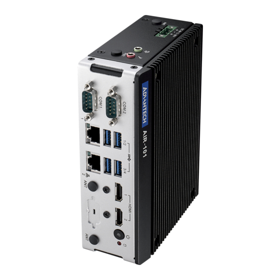
Page 23: System I/O
System I/O Front View COM2 COM1 USB 1/2 LAN1 USB 3/4 LAN2 HDMI1 HDMI2 ON/OFF Top View DC IN line Out Mic In AIR-101 User Manual... -
Page 24: External I/O
External I/O 2.4.1 Power On/Off Button AIR-101 features a Power On/Off button with an LED indicators on the top side that show On status (Green LED) Figure 2.1 Power On/Off Button 2.4.2 Power Input Connector The power input connector supports 12 ~ 28 V. The 3 pins are defined as +, -, and 2.4.3... -
Page 25: Usb 3.0 Connector
BI_DD-(GHz) 2.4.4 USB 3.0 Connector AIR-101 supports four USB 3.0 interfaces, which support Plug-and-Play functionality and hot swapping for up to 127 external devices. The USB interfaces comply with USB UHCI, Rev. 3.0. USB 3.0 connectors contain legacy pins to interface to USB 2.0 devices and a new set of pins for USB 3.0 connectivity. -
Page 26: Audio Connector
2.4.5 Audio Connector AIR-101 features two phone jack connectors that support stereo Line Out and Mic In audio ports. The audio chip is controlled by ALC888S and compliant with the Azalea standard. Figure 2.4 Audio Connector Table 2.6: Audio Connector Pin Definition... -
Page 27: Hdmi Connector
HDMI_TX2- HDMI_TX1+ HDMI_TX1- HDMI_TX0+ HDMI_TX0- HDMI_CLK+ HDMI_CLK- HDMI_DCLK HDMI_DDAT +V5_HDMI-HPD DDP0_HPD NC represents “No Connection”. 2.4.8 HDD LED Indicators AIR-101 provides one LED on the front panel that indicates the SSD/HDD status. Figure 2.7 HDD LED Indicators AIR-101 User Manual... -
Page 28: Antenna Socket
Each antenna socket is labeled “ANT” for easy identification. Figure 2.8 Antenna Socket 2.4.10 GPIO (Optional) AIR-101 offers a reserved 8-bit DI/O with the inclusion of an optional additional cable. M/B location: CN13 Table 2.9: HDMI Connector Pin Definition Signal Name... -
Page 29: Installation
Installation 2.5.1 M.2 Installation Loosen the 4 screws affixing screws and remove the bottom cover Install the M.2 2230 E key module AIR-101 User Manual... -
Page 30: Vega-320 And Amk-A0032 Thermal Kit Installation (Optional)
Reinstall the bottom cover and secure it with screws. 2.5.2 VEGA-320 and AMK-A0032 Thermal Kit Installation (Optional) Please follow previous section “M.2 Installation” to install the VEGA-320 mod- ule, and do not replace the bottom cover. Loosen the 4 screws and remove the rear cover. AIR-101 User Manual... - Page 31 Take the thermal pad with white protecting film. Carefully remove the film from both sides. Then attach the thermal pad to AMK-A0032 thermal kit on the side with SATA Slim SSD installed, as shown in the image below. Thermal pad with white protecting film AIR-101 User Manual...
- Page 32 Then attach the thermal pad to the other side of AMK-A0032 kit with SATA cable, as show in the image below. Thermal pad with blue protecting film Secure the 4 screws to the rear cover. AIR-101 User Manual...
- Page 33 Install the bottom cover with the 4 screws on the left and right sides of the sys- tem. AIR-101 User Manual...
-
Page 34: Optional Adaptor Installation
To install an optional adapter, connect the adapter wires to the 3-pin phoenix connector provided in the accessory box. Connect the wires to the correct +, -, and GND pins then fix in place using a screwdriver. Connect the 3-pin phoenix connector to the DC In port AIR-101 User Manual... -
Page 35: Bios Settings
Chapter BIOS Settings This chapter details the BIOS con- figuration instructions... -
Page 36: Introduction
All configuration data is stored in battery-backed CMOS to ensure the setup information is retained when the power is turned off. This chapter describes the basic navigation of the AIR-101 BIOS setup screens AIR-101 User Manual... -
Page 37: Entering Bios Setup
System Date using the <Arrow> keys. Enter new values via the keyboard. Press the <Tab> key or the <Arrow> keys to move between fields. The date must be entered in MM/DD/YY format, and the time must be entered in HH:MM:SS for- mat. AIR-101 User Manual... -
Page 38: Advanced Bios Setup
The options for any of the Advanced BIOS Setup items can be displayed by highlighting the item using the <Arrow> keys. The Advanced BIOS Setup page is shown below: AIR-101 User Manual... - Page 39 3.2.2.1 Trusted Computing Trust Computing provides security support for the device. AIR-101 User Manual...
- Page 40 This item allows users to enable or disable hibernation ACPI Sleep State This item allows users to set the ACPI sleep state Lock Legacy Resources This item allows users to lock legacy device resources AIR-101 User Manual...
- Page 41 Set Parameters of Serial Port 1 (COM 1) This item allows users to configure Serial Port 1 Set Parameters of Serial Port 2 (COM 2) This item allows users to configure Serial Port 2 AIR-101 User Manual...
- Page 42 This item allows users to specify the settings for a super I/O device Choose Serial Port Mode This item allows users to change the serial port mode RS485 Auto Flow This item allows users to enable or disable RS485 auto flow AIR-101 User Manual...
- Page 43 The items and options for configuring Serial Port 2 are the same as that for Serial Port 1 AIR-101 User Manual...
- Page 44 3.2.2.5 Hardware Monitor PC Health Status This shows all system information including the CPU/system temperature and voltage Watchdog Timer This item allows users to enable or disable the watchdog timer functions (before booting to OS) AIR-101 User Manual...
- Page 45 This item allows users to enable or disable Wake On Alarm Event. If the Fixed- Time option is selected for this item, the system will wake at the hr:min:sec specified. If the DynamicTime option is selected, the system will wake at the cur- rent time + specified minute(s). AIR-101 User Manual...
- Page 46 This item allows users to enable or disable console redirection for Microsoft Windows Emergency Management Services (EMS) Legacy Console Redirection This item allows users to configure the legacy console redirection serial port Console Redirection This item allows users to configure the console redirection settings AIR-101 User Manual...
- Page 47 3.2.2.8 CPU Configuration CPU Information This item allows users to view the CPU, speed, and core information AIR-101 User Manual...
- Page 48 This item allows users to enable or disable turbo mode Boot Performance Mode This item allows users to configure the boot performance mode for optimum per- formance C-States This item allows users to enable or disable C states AIR-101 User Manual...
- Page 49 3.2.2.9 PCI Subsystem Settings Above 4G Decoding Enables or Disables 64bit capable Devices to be Decoded in Above 4G Address Space (Only if System Supports 64 bit PCI Decoding). AIR-101 User Manual...
- Page 50 This item allows users to configure the maximum time the device will wait before reporting itself to the host controller. The Auto option uses the default value, which is 100 ms for a root port. For a hub port, the default delay time is deter- mined by the hub descriptor. AIR-101 User Manual...
- Page 51 This item allows users to configure the time the system waits before PXE boot Media Detect Count This item allows users to configure the number of times the system checks for the presence of media AIR-101 User Manual...
- Page 52 3.2.2.12 CSM Configuration AIR-101 User Manual...
- Page 53 This item allows users to configure the execution of UEFI and Legacy Storage OpROM Video This item allows users to configure the execution of UEFI and Legacy Video OpROM Other PCI Devices This item allows users to configure the OpROM execution policy for other devices AIR-101 User Manual...
- Page 54 3.2.2.13 Security Configuration TXE EOP Message This item allows users to enable or disable the sending of an EOP message before entering OS AIR-101 User Manual...
-
Page 55: Chipset Configuration
This item allows users to access and configure South Bridge items Uncore Configuration This item allows users to access and configure Uncore items South Cluster Configuration This item allows users to access and configure South Cluster items AIR-101 User Manual... - Page 56 3.2.3.1 North Bridge Max TOLUD This item allows users to configure the maximum value of TOLUD AIR-101 User Manual...
- Page 57 Serial IRQ Mode This item allows users to configure the serial IRQ mode SMBus Support This item allows users to enable or disable SMBus support OS Selection This item allows users to select the target OS AIR-101 User Manual...
- Page 58 This item allows users to select the DVMT5.0 total graphics memory size used by the internal graphics device GT PM Support This item allows users to enable or disable GT PM support PAVP Enable This item allows users to enable or disable PAVP AIR-101 User Manual...
- Page 59 This item allows users to access and configure the USB configuration settings Miscellaneous Configuration This item allows users to enable or disable miscellaneous functions/features HD-Audio Configuration Settings HD-Audio Support This item allows users to enable or disable HD audio support AIR-101 User Manual...
- Page 60 This item allows users to enable or disable the on-board LAN1 controller Onboard LAN2 Controller This item allows users to enable or disable the on-board LAN2 controller PCIE Wake from S5 This item allows users to enable or disable Wake from S5 via PCIE AIR-101 User Manual...
- Page 61 AIR-101 User Manual...
- Page 62 SATA controller supports two internal SATA ports (up to 3Gb/s per port). Port 1 This item allows users to enable or disable the SATA port SATA Device Type This item allows users to identify the SATA port connected to an SSD or HDD AIR-101 User Manual...
- Page 63 This item allows users to enable or disable the corresponding USB port from reporting a device connection to the controller. XHCI Disable Compliance Mode This item allows users to enable or disable XHCI compliance mode. The default setting is disabled. AIR-101 User Manual...
- Page 64 SMM-based flash protection. RTC Lock This item allows users to enable or disable the RTC lock feature. When enabled, bytes 38h ~ 3Fh in the lower/upper 128-byte bank of RTC RAM will be locked. AIR-101 User Manual...
-
Page 65: Security
Select the Security tab of the main BIOS Setup Utility menu. To access the sub menu for each item, select the item and press <Enter>. Change Administrator/User Password This item allows users to setup the administrator account and configure the user password settings AIR-101 User Manual... -
Page 66: Boot
This item allows users to enable or disable the FastBoot function. When enabled, most probes are skipped to reduce the time required for boot up. New Boot Option Policy This item allows users to configure the policy for newly detected UEFI boot options AIR-101 User Manual... -
Page 67: Save & Exit
This item allows users to save all configuration changes as user defaults Restore User Defaults This item allows users to restore the system configuration options to the user default settings Boot Override This item allows users to enable or disable the boot priority override function AIR-101 User Manual... - Page 68 AIR-101 User Manual...
-
Page 69: Watchdog Sample
Appendix Watchdog Sample Code... -
Page 70: Watchdog Function
;==================================================== ;66H ;WDT timer time-out value ;bit[7:0]=0~255 ;==================================================== mov dx,SCH3114_IO + 66h mov al,01h out dx,al ;==================================================== ;bit[0] status bit R/W ;WD timeout occurred =1;WD timer counting = 0 ;==================================================== mov dx,SCH3114_IO + 68h AIR-101 User Manual... - Page 71 .exit AIR-101 User Manual...
- Page 72 AIR-101 User Manual...
-
Page 73: Susi Api Introduction
Appendix SUSI API Introduction... -
Page 74: Susi Api Introduction
However, due to the inaccuracy of many commercially available hardware monitoring chips, Advantech has developed a unique scheme for hardware monitoring that uses a dedicated micro-processor with algorithms specifically designed for providing accu- rate, reliable, real-time data. - Page 75 AIR-101 User Manual...
- Page 76 No part of this publication may be reproduced in any form or by any means, such as electronically, by photocopying, recording, or otherwise, without prior written permission from the publisher. All brand and product names are trademarks or registered trademarks of their respective companies. © Advantech Co., Ltd. 2020...
Need help?
Do you have a question about the AIR-101 and is the answer not in the manual?
Questions and answers