
Related Manuals for Marvel MLDR224


Summary of Contents for Marvel MLDR224
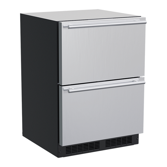
- Page 1 O W N E R S G U I D E M A R V E L U N D E R C O U N T E R R E F R I G E R A T I O N F O R M O D E L # M L D R 2 2 4 T H E O R I G I N A L R E F R I G E R A T I O N E X P E R T S S I N C E 1 8 9 2...
- Page 2 Got a Marvelous Design? The service number and serial number can be found on the We would love to see how your Marvel product looks in its serial plate which is located inside the cabinet on the left new home. Send us photos at marketing@marvelrefrigera- side near the top.
-
Page 3: Table Of Contents
TABLE OF CONTENTS Tip: Click on any section below to jump directly there Safety Important Safety Instructions Installation Unpacking Your Appliance Electrical Installing the anti-tip device Drawer Divider Integrated Panel Dimensions Integrated Panel Installation Maintenance Care and Cleaning Extended Non-Use Operating Instructions Energy Savng Tips Service... -
Page 4: Important Safety Instructions
IMPORTANT SAFETY INSTRUCTIONS Important Safety Instructions Warnings and safety instructions appearing in this guide are not meant to cover all possible conditions and situa- tions that may occur. Common sense, caution, and care must be exercised when installing, maintaining, or operat- ing this appliance. -
Page 5: Unpacking Your Appliance
UNPACKING YOUR APPLIANCE CAUTION WARNING If the appliance was shipped, handled, or stored in other EXCESSIVE WEIGHT HAZARD than an upright position for any period of time, allow the ap- Use two or more people to move product. pliance to sit upright for a period of at least 24 hours before Failure to do so can result in personal injury. -
Page 6: Electrical
ELECTRICAL Electrical Connection A grounded 115 volt, 15 amp dedicated circuit is required. This product is factory equipped with a power supply cord that has a three-pronged, grounded plug. It must be plugged into a mating grounding type receptacle in accor- dance with the National Electrical Code and applicable lo- Do not remove cal codes and ordinances (see Figure 4). -
Page 7: Installing The Anti-Tip Device
INSTALLING THE ANTI TIP DEVICE Anti-Tip WARNING Bracket Leveling Leg • ALL APPLIANCES CAN TIP RESULTING IN INJURY. • INSTALL THE ANTI-TIP Bottom View of ⁄ " BRACKET PACKED WITH Beverage (54.6 cm) THE APPLIANCE. Center • FOLLOW THE INSTRUC- TIONS BELOW Front of cabinet Anti-Tip Device... - Page 8 INSTALLING THE ANTI TIP DEVICE NOTE When the floor mounted anti-tip bracket is used the mini- mum adjusted height of the cabinet is increased by ⁄ " (9 mm). "V" notches Rear Leveling leg in bracket Figure 15a Screw ⁄ "...
-
Page 9: Drawer Divider
DRAWER DIVIDER Drawer Divider The top and bottom drawer have an adjustable drawer divider. To adjust the divider, making the 4 areas larger or smaller, move the center post along the length of the rods in either direction. See Figure 16 and 16a. The divider can also be removed from the drawer. -
Page 10: Integrated Panel Dimensions
INTEGRATED PANEL DIMENSIONS Panel ⁄ " thickness (603 mm) ⁄ " (379 mm) ⁄ " ⁄ " (302 mm) -
Page 11: Integrated Panel Installation
INTEGRATED PANEL INSTALLATION CAUTION It is important to use the factory provided grille that came with the product to assure proper air flow is maintained through the condenser. The use of a custom grille is not recommended and will void the warranty. Full Integrated Panel Installation Instructions Determine Wood Screw Requirements 1. - Page 12 INTEGRATED PANEL INSTALLATION Step 1: Remove Drawers from unit. Begin by pulling out the top drawer. Remove screws .35/.31 securing drawer to slides. Pull drawer forward, lift up (9 mm/7.5 mm) and out to clear clips in rear of drawer. Move drawer forward about 1"...
- Page 13 INTEGRATED PANEL INSTALLATION Step 3: Attach the Integrated Panel to the Drawer 1. Set the integrated panel on drawer front face and align edges. The custom integrated panel should be flush with the top of the drawer and centered on the width of the drawer.
-
Page 14: Care And Cleaning
CARE AND CLEANING Front Grille The following suggestions will minimize the Be sure that nothing obstructs the required air flow open- cost of operating your refrigeration appliance. ings in front of the cabinet. At least once or twice a year, 1. - Page 15 ENERGY SAVING TIPS The following suggestions will minimize the cost of operating your refrigeration appliance. 1. Do not install your appliance next to a hot appliance (cooker, dishwasher, etc.), heating air duct, or other heat sources. 2. Install product out of direct sunlight. 3.
-
Page 16: Extended Non-Use
Winterization If the unit will be exposed to temperatures of 40° F (5° C) or less, the steps above must be followed. For questions regarding winterization, please call Marvel at (616) 754-5601. CAUTION Damage caused by freezing temperatures is not covered... -
Page 17: Obtaining Service
OBTAINING SERVICE If Service is Required: • If the product is within the first year warranty period please contact your dealer or call Marvel Customer Service at 616.754.5601 for directions on how to obtain warranty coverage in your area. •... -
Page 18: Ordering Replacement Parts
Warranty parts will be shipped at no charge after Marvel confirms warranty status. Please provide the model, serial number, part number and part description. Some parts will require color or voltage information. - Page 19 Warranty parts will be shipped at no charge after Marvel confirms warranty status. Please provide the model, serial number, part number and part description. Some parts will require color or voltage information.
-
Page 20: R600A Specifications
PERSONNEL DO HOT PUNCTURE REFRIGERANT TUBING refrigeration system. RISK Of FIRE OR EXPLOSION. FIAMHA_ B LE REFRIGERANT USED. CONSULT Never substitute Marvel OEM replacement parts REPAIR IIANUAVOWHER'S GUIDE BEFORE ATTEMPTING TO SERVICE THIS PRODUCT. ALL SAFETY PRECAUTIONS HUST BE FOUOWEO. - Page 21 R-600A SPECIFICATIONS/LABELING WARNING R-600a equipped products are labeled (both the unit and the compressor). Only skilled and well trained service technicians permitted to service R-600a equipped products. R-600a is colorless and odorless. All tools and equipment must be approved for use with R-600a refrigerant.
- Page 22 Evacuate/reclaim via the piecing pliers to ensure the When re-brazing, the system must be purged with dry system is empty of R-600a before any system work is nitrogen and at least one access point open to the performed. atmosphere. When re-brazing, proper ventilation is required along with constant monitoring for the presence of R600a refrigerant.
- Page 23 The low side of the refrigeration system (evaporator, Proper ventilation during service is required. compressor and suction line) must be leak tested with the compressor off (equalized pressure). Never apply a torch to a charged R-600a refrigeration system. RECHARGING No air is ever to be allowed inside the refrigeration system Use OEM replacement service parts and do not alter the (R-600a refrigerant or dry nitrogen only).
-
Page 24: System Diagnosis Guide
System Diagnosis Guide REGRIGERATION SYSTEM DIAGNOSIS GUIDE System Suction Suction Compressor Condenser Capillary Evaporator Wattage Condition Pressure Line Discharge Tube Normal Normal Slightly Very hot Very hot Warm Cold Normal below room temperature Overcharge Higher than Very cold Slightly warm Hot to warm Cool Cold... -
Page 25: Compressor Specifications
Compressor Specifications EMX20CLC REFRIGERANT R600A DANGER VOLTAGE 115 VAC FREQUENCY 60 Hz START WINDING Electrocution can cause death or serious injury. 7 Ohm at 77 ° RUN WINDING 13 Ohm at 77 Burns from hot or cold surfaces can cause serious °... - Page 26 For designated Marvel Professional product, Marvel offers a one year extension of the two year warranty coverage from the date of purchase, free of charge. To take advantage of this third year warranty, you must register your product with Marvel within 60 days from the date of purchase at marvelrefrigeration.com and provide proof of purchase.
Need help?
Do you have a question about the MLDR224 and is the answer not in the manual?
Questions and answers
WHAT IS THE OVERALL DEPTH REQUIRED WITH THE ATTACHED PANEL
The overall depth required for the Marvel MLDR224 with the attached panel is 23¾ inches (603 mm).
This answer is automatically generated