Table of Contents

Related Manuals for ECG M542


Summary of Contents for ECG M542
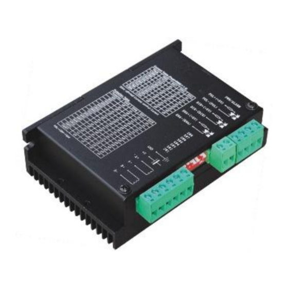
- Page 1 User’s Manual M542 High Performance Microstepping Driver Version 1.0 2012 All Rights Reserved Attention: Please read this manual carefully before using the driver! Easy Commercial Global Technology Co., LTD *** Savebase ***...
-
Page 2: All Rights Reserved
M542 Microstepping Driver Manual V1.0 ECG Safety Statement Easy Commercial Global is not liable or responsible for any accidents, injuries, equipment damage, property damage, loss of money or loss of time resulting from improper use of electrical or mechanical or software products sold on this website or other Easy Commercial Global sales resources. -
Page 3: Introduction, Features And Applications
1. Introduction, Features and Applications Introduction The M542 is a high performance microstepping driver based on pure-sinusoidal current control technology. Owing to the above technology and the self-adjustment technology (self-adjust current control parameters) according to different motors, the driven motors can run with smaller noise, lower heating, smoother movement and have better performances at higher speed than most of the drivers in the markets. -
Page 4: Pin Assignment And Description
3. Pin Assignment and Description The M542 has two connectors, connector P1 for control signals connections, and connector P2 for power and motor connections. The following tables are brief descriptions of the two connectors. More detailed descriptions of the pins and related issues are presented in section 4, 5, 9. -
Page 5: Connector P2 Configurations
M542 Microstepping Driver Manual V1.0 Selecting Control Signal Mode There is a jumper J1 inside the M542 specifically for selecting control signal mode, as shown in figure 2. Default setting is PUL/DIR mode. Figure 2: J1 Connector P2 Configurations Pin Function Details Power supply, 20~50 VDC, Including voltage fluctuation and EMF voltage. -
Page 6: Connecting The Motor
Figure 4: Connection to PNP signal (common-cathode) 5. Connecting the Motor The M542 can drive any 2-pahse and 4-pahse hybrid stepping motors. Connections to 4-lead Motors 4 lead motors are the least flexible but easiest to wire. Speed and torque will depend on winding inductance. In setting the driver output current, multiply the specified phase current by 1.4 to determine the peak output current. -
Page 7: Connections To 8-Lead Motors
M542 Microstepping Driver Manual V1.0 Figure 6: 6-lead motor half coil (higher speed) connections Full Coil Configurations The full coil configuration on a six lead motor should be used in applications where higher torque at lower speeds is desired. This configuration is also referred to as full copper. -
Page 8: Power Supply Selection
6. Power Supply Selection The M542 can match Large and small size stepping motors (from Nema size 17 to 34) made by us or other motor manufactures around the world. To achieve good driving performances, it is important to select supply voltage and output current properly. -
Page 9: Microstep Resolution Selection
4.5A 3.2A Notes: Ref Current table on the screen printing is used for the users of the M542 to refer. Due to motor inductance, the actual current in the coil may be smaller than the dynamic current setting, particularly under high speed condition. -
Page 10: Wiring Notes
M542 Microstepping Driver Manual V1.0 Standstill current setting SW4 is used for this purpose. OFF meaning that the standstill current is set to be half of the selected dynamic current and ON meaning that standstill current is set to be the same as the selected dynamic current. -
Page 11: Sequence Chart Of Control Signals
M542 Microstepping Driver Manual V1.0 10. Sequence Chart of Control Signals In order to avoid some fault operations and deviations, PUL, DIR and ENA should abide by some rules, shown as following diagram: Figure 11: Sequence chart of control signals Remark: a) T1: ENA must be ahead of DIR by at least 5s. - Page 12 M542 Microstepping Driver Manual V1.0 Problem Symptoms and Possible Causes Email: ebay@savebase.com Web: http://stores.ebay.co.uk/SAVEBASE...
Need help?
Do you have a question about the M542 and is the answer not in the manual?
Questions and answers