Table of Contents
Advertisement
Quick Links
Advertisement
Table of Contents

Related Manuals for Asus ESC9000G4


Summary of Contents for Asus ESC9000G4
- Page 1 ESC8000 G4 Series 4U Rackmount Server User Guide...
- Page 2 ASUSTeK COMPUTER INC. (“ASUS”). ASUS provides this manual “as is” without warranty of any kind, either express or implied, including but not limited to the implied warranties or conditions of merchantability or fitness for a particular purpose. In no...
-
Page 3: Table Of Contents
Installing the 2.5-inch SATA/SAS/NVME storage device ..2-18 Expansion slots ..................2-20 2.5.1 The PCI Express riser card ............2-20 2.5.2 Installing an ASUS PIKE II card ..........2-23 2.5.3 Installing an M.2 expansion card..........2-28 Cable connections ................... 2-30 Removable/optional components ............2-33 2.7.1... - Page 4 Internal LEDs ....................4-9 Internal connectors .................. 4-11 Chapter 5: BIOS Setup Managing and updating your BIOS ............5-2 5.1.1 ASUS CrashFree BIOS 3 utility........... 5-2 5.1.2 ASUS EZ Flash Utility ..............5-3 5.1.3 BUPDATER utility ............... 5-4 BIOS setup program .................. 5-6 5.2.1...
- Page 5 Contents Advanced menu ..................5-14 5.5.1 Trusted Computing..............5-15 5.5.2 ACPI Settings ................5-15 5.5.3 Smart Settings................5-16 5.5.4 Super IO Configuration ............. 5-16 5.5.5 Serial Port Console Redirection ..........5-17 5.5.6 Onboard LAN Configuration ............. 5-20 5.5.7 APM ..................5-21 5.5.8 PCI Subsystem Settings ............
- Page 6 Contents Chapter 6: RAID Configuration Setting up RAID ..................6-2 6.1.1 RAID definitions ................6-2 6.1.2 Installing hard disk drives ............6-3 6.1.3 Setting the RAID item in BIOS ............ 6-3 6.1.4 RAID configuration utilities ............6-3 ® Intel Rapid Storage Technology enterprise SATA Option ROM Utility ....................
- Page 7 ESC8000 G4 block diagram (Dual Root) ..............2 ESC8000 G4/10G block diagram (Single Root) ............3 ESC8000 G4/10G block diagram (Dual Root) ............3 Changing System PCI-E Topology ................4 Q-Code table ........................ 6 Notices ........................9 ASUS contact information ..................12...
-
Page 8: Safety Information
Safety information Electrical Safety • Before installing or removing signal cables, ensure that the power cables for the system unit and all attached devices are unplugged. • To prevent electrical shock hazard, disconnect the power cable from the electrical outlet before relocating the system. -
Page 9: About This Guide
About this guide Audience This user guide is intended for system integrators, and experienced users with at least basic knowledge of configuring a server. Contents This guide contains the following parts: Chapter 1: Product Introduction This chapter describes the general features of the server, including sections on front panel and rear panel specifications. - Page 10 Refer to the following sources for additional information, and for product and software updates. ASUS Control Center (ACC) user guide This manual tells how to set up and use the proprietary ASUS server management utility. ASUS websites The ASUS websites worldwide provide updated information for all ASUS hardware and...
-
Page 11: Chapter 1: Product Introduction
Chapter 1: Product Introduction Product Introduction This chapter describes the general features of the chassis kit. It includes sections on front panel and rear panel specifications. -
Page 12: System Package Contents
8 x Mylar for GPU air duct for AMD GPU 2 x CPU coolers 1 x Rail Kit 16 x VGA power cables 8 x ASUS CPU 8-pin Power cables 2 x CPU carriers One Row SYS FAN (Redundant FAN-Optional) 1 x Redundant Power Supply Module... -
Page 13: Serial Number Label
1.2 Serial number label Before requesting support from the ASUS Technical Support team, you must take note of the product’s serial number containing 12 characters such as xxS0xxxxxxxx. See the figure below. With the correct serial number of the product, ASUS Technical Support team members can then offer a quicker and satisfying solution to your problems. -
Page 14: System Specifications
1.3 System specifications The ASUS ESC8000 G4 Series servers features the ASUS Z11PG-D24 Series server board. The server supports Intel Xeon Scalable Processors Family Series plus other latest ® ® technologies through the chipsets onboard. Model Name ESC8000 G4 ESC8000 G4/10G 2 x Socket P0 (LGA 3647) - Page 15 Optional kits: ASUS PIKE II 3008 8-port SAS HBA card SAS Storage Controller ASUS PIKE II 3108 8-port SAS HW RAID card 12G SAS Support 8 x Hot-swap 2.5-inch Storage Bays - Storage bay 1 & 2 support NVMe/SATA/SAS* drives Storage Device Bays - Storage bay 3 - 8 support SATA/SAS* drives - Storage bay location numbers are from top to bottom.
- Page 16 Operating temperature: 10°C ~ 35°C Environment Non operating temperature: -40°C ~ 70°C Non operating humidity: 20% ~ 90% (Non-condensing) • Specifications are subject to change without notice. • Refer to www.asus.com for the latest OS AVL update. Chapter 1: Product Introduction...
-
Page 17: Front Panel Features
Message LED 2.5-inch Bay 1-8 Storage Device Access LED 1.5 Rear panel features The LAN ports and system power socket are located on the rear panel of the server. Half-length/Low-profile expansion slot Full-length/Full-height expansion slots Power cord connector and Redundant power supply The Dedicated Management LAN port is for the ASUS ASMB9-iKVM only. ASUS ESC8000 G4 Series... -
Page 18: Internal Features
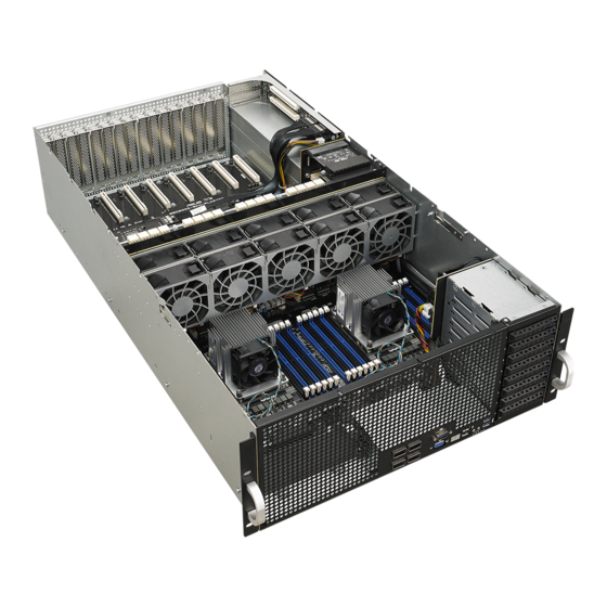
1.6 Internal features The barebone server includes the basic components as shown. Redundant Power Supply (hidden) ASUS Z11PG-D24 Series server Board System fans (second row of fans are optional) 8 x Hot-swap 2.5-inch Storage Bays PCIE SKU board with eight full-height/full-length... -
Page 19: Led Information
A hardware monitor event is indicated Normal status Location button Location switch is pressed with LED (Press the location switch again to turn off) No LAN connection Blinking LAN LEDs LAN is transmitting or receiving data LAN connection is present ASUS ESC8000 G4 Series... -
Page 20: Lan (Rj-45) Leds
Description Status Description No link 10 Mbps connection GREEN Linked ORANGE 100 Mbps connection BLINKING Data activity GREEN 1 Gbps connection Dedicated Management LAN LEDs (for ASUS ASMB9-iKVM and DM_LAN1) ACT/LINK LED SPEED LED Status Description Status Description No link 10 Mbps connection ORANGE Linked ORANGE 100 Mbps connection BLINKING... -
Page 21: Storage Device Status Led
SATA/SAS storage device power ON Storage device has failed and should be swapped immediately GREEN/ Blinking RAID rebuilding GREEN/ Blinking Locate GREEN/ Storage device not found GREEN Blinking Read/write data from/into the SATA/SAS storage device ASUS ESC8000 G4 Series 1-11... - Page 22 1-12 Chapter 1: Product Introduction...
-
Page 23: Chapter 2: Hardware Setup
Chapter 2: Hardware Setup Hardware Setup This chapter lists the hardware setup procedures that you have to perform when installing or removing system components. -
Page 24: Chassis Cover
Chassis cover There are three parts of the chassis cover you may remove. The diagrams in this section are for reference only. The system layout may vary with models, but the installation steps are the same for all models. To remove the rear chassis cover: Release the two (2) thumbscrews on the rear of the chassis. - Page 25 Slide the chassis cover towards the front to disengage it from the chassis and lift the chassis cover to completely remove it from the chassis. A protection film is pre-attached to the system cover before shipping. Please remove the protection film before turning on the system for proper heat dissipation. ASUS ESC8000 G4 Series...
-
Page 26: Air Duct
2.1.1 Air duct The diagrams in this section are for reference only. The system layout may vary with models, but the installation steps are the same for all models. To remove the air ducts: Remove the four (4) screws. Lift the top air duct to remove it from the chassis. Lift the bottom air duct to remove it from the motherboard. - Page 27 Align and reinstall the top and bottom air ducts into the chassis, ensuring that the screw holes on the air ducts match the screw holes on chassis. Secure the air ducts to the chassis with the four (4) screws removed earlier. ASUS ESC8000 G4 Series...
-
Page 28: Central Processing Unit (Cpu)
Contact your retailer immediately if the PnP cap is missing, or if you see any damage to the PnP cap/socket contacts/motherboard components. ASUS will shoulder the cost of repair only if the damage is shipment/ transit-related. - Page 29 Align the coolers in the correct orientation, then place the coolers on top of the CPU sockets. The CPU and CPU Carrier fits in only one correct orientation. DO NOT force the CPU and CPU Carrier into the socket to prevent damaging the CPU pins on the socket. ASUS ESC8000 G4 Series...
- Page 30 Twist each of the four (4) screws with a screwdriver just enough to attach the cooler to the motherboard. When the four (4) screws are attached, tighten them one by one in a diagonal sequence to completely secure the cooler. The cooler screws are T30 models.
-
Page 31: System Memory
System memory 2.3.1 Overview The motherboard comes with 24 Double Data Rate 4 (DDR4) Dual Inline Memory Modules (DIMM) sockets. The figure illustrates the location of the DDR4 DIMM sockets: ASUS ESC8000 G4 Series... -
Page 32: Memory Configurations
128GB, 256GB, and 512GB DCPMMs into the DIMM sockets using the memory configurations in this section. • Refer to ASUS Server AVL for the updated list of compatible DIMMs. • Always install DIMMs with the same CAS latency. For optimum compatibility, it is recommended that you obtain memory modules from the same vendor. - Page 33 2 DIMMs 4 DIMMs • • • 8 DIMMs 12 DIMMs • • • 16 DIMMs • • • • • • • • • 20 DIMMs 24 DIMMs • • • • • • ASUS ESC8000 G4 Series 2-11...
- Page 34 ® Intel DC persistent memory population table 1 CPU Configuration 1 CPU Configuration (must be on CPU1) Modes DIMM_F2 DIMM_F1 DIMM_E2 DIMM_E1 DIMM_D2 DIMM_D1 DCPMM DRAM 1 DCPMM DRAM 1 DCPMM DRAM 1 DCPMM DRAM 1 DCPMM DRAM 1 DCPMM DRAM 1 DCPMM DRAM 3...
- Page 35 DRAM1 DRAM 3 DCPMM DRAM 3 DCPMM DRAM3 AD+MM DCPMM DRAM 1 DRAM1 DCPMM DRAM 1 DRAM1 DCPMM DRAM 3 DRAM3 AD+MM DCPMM DRAM 1 DRAM 1 DRAM 1 DRAM1 (continued on the next page) ASUS ESC8000 G4 Series 2-13...
- Page 36 2 CPU Configuration (symmetric population) Modes DIMM_M2 DIMM_M1 DIMM_L2 DIMM_L1 DIMM_K2 DIMM_K1 DCPMM DRAM 1 DCPMM DRAM 1 DCPMM DRAM 1 DCPMM DRAM 1 DCPMM DRAM 1 DCPMM DRAM 1 AD+MM DCPMM DRAM 3 DCPMM DRAM 3 DCPMM DRAM 3 DRAM 1 DRAM 1 DCPMM...
- Page 37 Asymmetric Population (2nd Socket has no DCPMM DIMM) Modes DIMM_J2 DIMM_J1 DIMM_H2 DIMM_H1 DIMM_G2 DIMM_G1 DRAM 1 DRAM 1 DRAM 1 AD - APP DIRECT MODE DRAM1 - RDIMM, RDIMM 3DS, LRDIMM, LRDIMM 3DS DCPMM - DC PERSISTENT MEMORY ASUS ESC8000 G4 Series 2-15...
- Page 38 2 CPU Configuration with 2 DCPMM DIMMs (asymmetric population) 2 CPU Configuration (asymmetric population) Modes DIMM_F2 DIMM_F1 DIMM_E2 DIMM_E1 DIMM_D2 DIMM_D1 DRAM 1 DRAM 1 DRAM 1 2 CPU Configuration (asymmetric population) Modes DIMM_C2 DIMM_C1 DIMM_B2 DIMM_B1 DIMM_A2 DIMM_A1 DRAM 1 DRAM 1 DCPMM DRAM 1...
-
Page 39: Installing A Dimm On A Single Clip Dimm Socket
Press the retaining clip outward to unlock the DIMM. Remove the DIMM from the socket. Support the DIMM lightly with your fingers when pressing the retaining clips. The DIMM might get damaged when it flips out with extra force. ASUS ESC8000 G4 Series 2-17... -
Page 40: Storage Devices
Storage devices The ESC8000 G4 Series system supports hot-swap 2.5-inch SATA/SAS/NVME storage devices. The storage device installed in the storage bay connects to the motherboard SATA/ SAS/NVME ports via the SATA/SAS/NVME backplane. 2.4.1 Installing the 2.5-inch SATA/SAS/NVME storage device NVME storage devices are only supported on the top 2 (two) storage bays. If you wish to install an NVME storage device, ensure to install them to the 2 (two) top storage bays. - Page 41 Push the tray lever until it clicks and secures the storage device tray in place. Repeat steps 1 to 7 to install the other storage devices. ASUS ESC8000 G4 Series 2-19...
-
Page 42: Expansion Slots
Expansion slots Ensure to unplug the power cord before adding or removing expansion cards. Failure to do so may cause you physical injury and damage motherboard components. 2.5.1 The PCI Express riser card The server system comes pre-installed with a riser card that supports two x16 slots (Gen3 x16 link) for installing PCI-E x16 low profile of half-length cards. - Page 43 Align and insert the riser card and expansion card assembly into the chassis, then slide the riser card and expansion card assembly towards the rear of the chassis to lock it in place. ASUS ESC8000 G4 Series 2-21...
- Page 44 Secure the riser card and expansion card assembly with the two (2) screws that you removed earlier in step 1. 2-22 Chapter 2: Hardware Setup...
-
Page 45: Installing An Asus Pike Ii Card
2.5.2 Installing an ASUS PIKE II card Remove the two (2) screws on the ASUS PIKE II card bracket (A), then remove the ASUS PIKE II card bracket (B) from the chassis. ASUS PIKE II card bracket Prepare the ASUS PIKE II card. - Page 46 Connect the mini-SAS HD cables to the ASUS PIKE II card (A), insert the ASUS PIKE II card and the ASUS PIKE II card bracket into the PCI-E slot on the motherboard (B), then secure it with the two (2) screws that you removed earlier (C).
- Page 47 Remove the default cable from the backplane (A), then connect the other end of the mini-SAS HD cables from the ASUS PIKE II card to the SATA/SAS backplane. Rear view Connect from ASUS PIKE II card slot 1 Connect from ASUS...
- Page 48 Align the three screw holes on the Cache Vault Power Module clip to the three screw holes on the Cache Vault bracket, then secure the clip with the bundled three (3) screws and three (3) bundled nuts. Align and install the Cache Vault Power Module into the Cache Vault Power Module clip.
- Page 49 (A), then secure it with the two (2) screws removed earlier (B). Connect the cable extender to the Cache Vault Flash Module (A), then connect the cable to the Cache Vault Power Module (B) to complete. ASUS ESC8000 G4 Series 2-27...
-
Page 50: Installing An M.2 Expansion Card
2.5.3 Installing an M.2 expansion card You can install an M.2 expansion card on the provided M.2 slot onboard (supports up to 22110). To install an M.2 expansion card: Remove the screw on the M.2 socket and put it aside. Prepare your M.2 expansion card. - Page 51 • Please pay attention when removing the screw, the stand screw might be removed together with it. • Ensure that the M.2 card is positioned between the screw and the stand screw before securing it. ASUS ESC8000 G4 Series 2-29...
-
Page 52: Cable Connections
Cable connections • The bundled system cables are pre-connected before shipment. You do not need to disconnect these cables unless you remove the pre-installed components to install additional devices. • Refer to Chapter 4 for detailed information on the motherboard connectors. Motherboard VGA_SW1 PSUSMB1... - Page 53 PCIE SKU board ESC8000-SKU-PLX8796 SLMPCIE6 SLMPCIE8 SLMPCIE5 SLMPCIE7 PWR_CON3 PWR_CON2 SLMPCIE2 SLMPCIE1 SLMPCIE4 SLMPCIE3 PWR_CON1 SATA/SAS backplane ASUS ESC8000 G4 Series 2-31...
- Page 54 Pre-connected system cables 8-pin BPPWR1 power connector (from motherboard to SATA/SAS backplane) Panel connector (from motherboard to front I/O board) Auxiliary panel 1 connector (from motherboard to front I/O board) OCU-USB to USB connector (from motherboard to front I/O board) OCU-PCIE to PCIE connector (from motherboard to SATA/SAS backplane) OCU-LAN to LAN connector (from motherboard to rear I/O board) 20-pin SSI power connectors (from power distribution board to motherboard)
-
Page 55: Removable/Optional Components
Set the fan aside. Repeat steps 1 to 2 to uninstall the other GPU fans. To reinstall the GPU fans, insert the fan into the fan cage. Ensure the fan connector is seated firmly within the cable holder. ASUS ESC8000 G4 Series 2-33... -
Page 56: Redundant Power Supply Units
2.7.2 Redundant power supply units We recommend that you use both of your hands in performing the following steps. To replace a power supply unit (PSU): Lift up the PSU lever. Hold the PSU lever, press the PSU latch (A) then carefully pull the PSU out of the system chassis (B). - Page 57 (e.g. 1 x 1620 W + 1 x 2000 W) may yield unstable results and potential damage to your system. • For a steady power input, use only the power cables that come with the server system package. ASUS ESC8000 G4 Series 2-35...
-
Page 58: Installing Gpu Cards
Installing GPU cards • Use both of your hands in performing the following steps. • Read the documentation that comes with your GPU card before installing them. • When installing more than one GPU card, it is recommended to install the card on PCIE1 slot first. - Page 59 CPU-12V or above GPU cards, prepare the GPU card dongle or power cable. Nvidia CPU-12V GPU card dongle ASUS CPU 8-pin power cable A dongle may be required to connect the The ASUS CPU 8-pin power system’s GPU power cable to the GPU cable may be used to connect to ®...
- Page 60 CPU-12V or above GPU cards with power cable and Nvidia CPU-12V GPU card dongle Power cable ® Nvidia CPU-12V GPU card dongle ® Nvidia CPU-12V or above GPU cards with ASUS CPU 8-pin power cable ASUS CPU 8-pin power cable 2-38 Chapter 2: Hardware Setup...
- Page 61 Notch for the power cable (or power cable and dongle) From inside the air duct, secure the air duct to the GPU card with two (2) screws. Notch for the cable ASUS ESC8000 G4 Series 2-39...
- Page 62 Attach the other end of the power cable (6-pin power connector) to an available 6-pin power connector on the middle of the server system (A), align and insert the golden fingers of the GPU card into the PCIE slot on the PCIE SKU board (B), then secure the GPU card with the two (2) screws that you removed earlier in step 1 (C).
-
Page 63: Chapter 3: Installation Options
Chapter 3: Installation Options Installation Options This chapter describes how to install the optional components and devices into the barebone server. -
Page 64: Rail Kit
Rail Kit The rail kit package includes: 2 x 1200 mm rack rails (or 2 x 1000 mm rack rails) Rack rails Rear end Front end 4 x M4X4L screws 4 x #6-32X4L screws 8 x #10-32 screws 8 x ø17.1 screws (or 10 x #10-32 screws for 1000 mm rack rails) 2 x M5X20L screws •... -
Page 65: Attaching The Rack Rails
Installing the rack rail To install the rack rails into the rack: 1. Select a desired space on the rack. A 1U space consists of three square mounting holes with two thin lips on the top and the bottom. Align and insert the front end of the Front rack post Front end of rack rail appropriate rack rail (left and right) into the front rack post. ASUS ESC8000 G4 Series... - Page 66 Press the spring lock on the rear end Rear rack post of the rack rail and insert the studs into Spring lock the selected mounting holes on the rear rack post. Rear end of rack rail Slide the intermediate rail out of the outer rail until it clicks to a stop. Intermediate rail Outer rail Slide the inner rail out of the intermediate rail until it clicks to a stop. Slide the white release tab outwards and remove the inner rail completely from the intermediate rail. Inner rail Intermediate rail Blue release tab White release tab The blue release tab is available on 1200 mm rack rails. This blue release tab is used to further extend or retract the inner rail. Repeat steps 2 to 5 for the other rack rail.
- Page 67 Align the inner rails with the studs on both sides of the server system, install the inner rails to the server system, then slide the inner rails toward the rear of the server system until it locks in place. Secure the inner rails on both sides of the server system using the #6-32X4L screws. ASUS ESC8000 G4 Series...
- Page 68 Align the server system and gently insert it into the rack rails. 10. (optional) Use the M5X20L screws to Front rack post Front end of rack rail secure the rack rails to the rack post. 11. Gently push the server system until it is completely installed into the rack rail. (optional) For 1200 mm rack rails, if the inner rail clicks to a stop while you are installing the server system into the rack rails, slide the blue release tab outwards and gently push the server system until it is completely installed into the rack rail. Inner rail Intermediate rail Blue release tab White release tab The blue release tab is available on 1200 mm rack rails. This blue release tab is used to further extend or retract the inner rail.
- Page 69 ESC8000 G4 Series Front View ASUS ESC8000 G4 Series...
-
Page 70: Cable Management Arm (Optional For 1200 Mm Rack Rails)
Cable management arm (optional for 1200 mm rack rails) You can install an additional cable management arm (CMA) to the rack rails to help you manage the cables from your server system. The CMA is designed with movable parts that allow you to move the server system along the rack rail without the need to remove the CMA. Outer receptor Hook and loop fasteners Inner receptor Pivot receptor Cable fasteners 3.2.1 Attaching the cable management arm Installing the cable management arm To install the cable management arm: 1. - Page 71 The installation steps in this section uses a Left pivot configuration as an example, the installation steps for a Right pivot configuration is similar. Align and connect the inner receptor on the CMA with the connector on the inner rail. Align and connect the outer receptor on the CMA with the connector on the intermediate rail. ASUS ESC8000 G4 Series...
- Page 72 Align and connect the pivot receptor on the CMA with the connector on the other intermediate rail. Pass the cables from the server system through the hook and loop fasteners and the cable fasteners on the CMA to complete. Hook and loop fasteners Cable fasteners 3-10 Chapter 3: Installation Options...
-
Page 73: Chapter 4: Motherboard Information
Chapter 4: Motherboard Information Motherboard Information This chapter includes the motherboard layout and brief descriptions of the jumpers and internal connectors. -
Page 74: Z11Pg-D24 Series Motherboard Layout
Z11PG-D24 Series Motherboard layout Chapter 4: Motherboard Information... - Page 75 VROC_KEY connector (4-pin VROC_KEY) 4-20 System Management Bus (SMBUS) connector (5-1 pin SMBUS1) 4-24 IPMI SW setting (3-pin IPMI_SW1) ME firmware force recovery setting (3-pin ME_RCVR1) PCH_MFG1 setting (3-pin PCH_MFG1) Micro SD card slot (MSD1) 4-19 ASUS ESC8000 G4 Series...
-
Page 76: Jumpers
Jumpers Clear RTC RAM (3-pin CLRTC1) This jumper allows you to clear the Real Time Clock (RTC) RAM in CMOS. You can clear the CMOS memory of date, time, and system setup parameters by erasing the CMOS RTC RAM data. The onboard button cell battery powers the RAM data in CMOS, which include system setup information such as system passwords. - Page 77 This jumper allows you to enable or disable the onboard VGA controller. Set to pins 1–2 to activate the VGA feature. IPMI SW setting (3-pin IPMI_SW1) This jumper allows you to select which protocol in the GPU sensor to function. ASUS ESC8000 G4 Series...
- Page 78 ME firmware force recovery setting (3-pin ME_RCVR1) This jumper allows you to quickly recover the Intel Management Engine (ME) firmware when it becomes corrupted. Baseboard Management Controller setting (3-pin BMC_EN1) This jumper allows you to enable (default) or disable on-board BMC. Ensure to set this BMC jumper to enabled to avoid system fan control and hardware monitor error.
- Page 79 DDR4 thermal event setting (3-pin DIMMTRIP1-2) These jumpers allow you to enable or disable DDR4 DIMM thermal sensing event pin. PCH_MFG1 setting (3-pin PCH_MFG1) This jumper allows you to update the BIOS ME block. ASUS ESC8000 G4 Series...
- Page 80 Smart Ride Through (SmaRT) setting (3-pin SMART_PSU1) This jumper allows you to enable or disable the Smart Ride Through (SmaRT) function. This feature is enabled by default. Set to pins 2-3 to disable it. When enabled, SmaRT allows uninterrupted operation of the system during an AC loss event. DMLAN setting (3-pin DM_IP_SEL1) This jumper allows you to select the DMLAN setting.
-
Page 81: Internal Leds
The illustration below shows the location of the onboard LED. BMC LED (BMCLED1) The BMC LED lights up to indicate that the on-board BMC is functional. ASUS ESC8000 G4 Series... - Page 82 CATT LED (CATTERR1) The CATT LED indicates that the system has experienced a fatal or catastrophic error and cannot continue to operate. 4-10 Chapter 4: Motherboard Information...
-
Page 83: Internal Connectors
The SLMPCIE23 connector supports two PCIe x4 and two sSATA signals. Mini-SAS HD connector (ISATA1-2; REARIO1) This motherboard comes with mini Serial Attached SCSI (SAS) HD connectors, the storage technology that supports Serial ATA. Each connector supports up to four devices. ASUS ESC8000 G4 Series 4-11... - Page 84 Hard disk activity LED connector (4-pin HDLED1) This LED connector is for the storage add-on card cable connected to the SATA or SAS add-on card. The read or write activities of any device connected to the SATA or SAS add-on card causes the front panel LED to light up. TPM connector (20-1 pin TPM1) This connector supports a Trusted Platform Module (TPM) system, which can securely store keys, digital certificates, passwords, and data.
- Page 85 DO NOT forget to connect the fan cables to the fan connectors. Insufficient air flow inside the system may damage the motherboard components. These are not jumpers! DO NOT place jumper caps on the fan connectors! ASUS ESC8000 G4 Series 4-13...
- Page 86 System panel connector (20-pin PANEL1) This connector supports several chassis-mounted functions. System power LED (3-pin PLED) This 3-pin connector is for the system power LED. Connect the chassis power LED cable to this connector. The system power LED lights up when you turn on the system power, and blinks when the system is in sleep mode.
- Page 87 These leads are for the locator button on the front panel. This button queries the state of the system locator. LAN activity LED and USB port (USB power and OC pin) These leads are for the USB ports on the front or rear panel. ASUS ESC8000 G4 Series 4-15...
- Page 88 SSI power connectors (24-pin PWR1-2) These connectors are for the SSI power supply plugs. The power supply plugs are designed to fit these connectors in only one orientation. Find the proper orientation and push down firmly until the connectors completely fit. •...
- Page 89 This connector is for the power supply plugs that connects to the PCIE SKU board. The power supply plugs are designed to fit these connectors in only one orientation. Find the proper orientation and push down firmly until the connectors completely fit. ASUS ESC8000 G4 Series 4-17...
- Page 90 M.2 board power connector (4-pin PWR_M2) This connector is for the power supply plugs that connects to the M.2 board. The power supply plugs are designed to fit these connectors in only one orientation. Find the proper orientation and push down firmly until the connectors completely fit. Rear LAN panel power connector (4-pin LAN_PWR1) This connector is for the power supply plugs that connects to the rear LAN panel.
- Page 91 Memory Card, then reboot the system to access the Memory Card. Some memory cards may not be compatible with your motherboard. Ensure that you use only compatible memory cards to prevent loss of data, damage to your device, or memory card, or both. ASUS ESC8000 G4 Series 4-19...
- Page 92 VROC_KEY connector (4-pin VROC_KEY1) This connector allows you to connect a KEY module to support Intel VMD RAID function. PCIE expansion slot (PCIE11) The onboard PCIE11 slot provides one Gen3 x8 link. This slot supports HBA/RAID cards and various server class high performance add-on cards. 4-20 Chapter 4: Motherboard Information...
- Page 93 USB 3.0 including faster data transfer speeds of up to 5 Gbps, faster charging time for USB-chargeable devices, optimized power efficiency, and backward compatibility with USB 2.0. (OCUUSB1 connector is used for the front USB panel by default). The USB port module is purchased separately. ASUS ESC8000 G4 Series 4-21...
- Page 94 OCUPCIE connectors (OCUPCIE13-14) Connects the PCIE signal to the front riser card or NVME port on the backplane. OCULAN connectors (OCULAN1) Connects the PCIE signal to the LAN port on the back panel. 4-22 Chapter 4: Motherboard Information...
- Page 95 This connector allows you to connect SMBus (System Management Bus) to the power supply unit to read PSU information. Devices communicate with an SMBus host and/or other SMBus devices using the SMBus interface. VGA connector (16-pin VGA_HDR1) This connector supports the VGA High Dynamic-Range interface. ASUS ESC8000 G4 Series 4-23...
- Page 96 System Management Bus (SMBUS) connector (5-1 pin SMBUS1) This connector controls the system and power management-related tasks. This connector processes the messages to and from devices rather than tripping the individual control lines. Serial port connector (10-1 pin COM1) This connector is for a serial (COM) port. Connect the serial port module cable to this connector, then install the module to a slot opening at the back of the system chassis.
- Page 97 This port functions only when you enable ASMB9 Management card. Dedicated Management LAN port (DM_LAN1) LED indications Activity/Link LED Speed LED Status Description Status Description No link 10 Mbps connection ORANGE Linked ORANGE 100 Mbps connection BLINKING Data activity GREEN 1 Gbps connection ASUS ESC8000 G4 Series 4-25...
- Page 98 4-26 Chapter 4: Motherboard Information...
-
Page 99: Chapter 5: Bios Setup
Chapter 5: BIOS Setup BIOS Setup This chapter tells how to change system settings through the BIOS Setup menus and describes the BIOS parameters. -
Page 100: Managing And Updating Your Bios
BIOS in the future. Copy the original motherboard BIOS using the BUPDATER utility. 5.1.1 ASUS CrashFree BIOS 3 utility The ASUS CrashFree BIOS 3 is an auto recovery tool that allows you to restore the BIOS file when it fails or gets corrupted during the updating process. You can update a corrupted BIOS file using a USB flash drive that contains the updated BIOS file. -
Page 101: Asus Ez Flash Utility
5.1.2 ASUS EZ Flash Utility The ASUS EZ Flash Utility feature allows you to update the BIOS without having to use a DOS-based utility. Before you start using this utility, download the latest BIOS from the ASUS website at www.asus.com. To update the BIOS using EZ Flash Utility: Insert the USB flash disk that contains the latest BIOS file into the USB port. Enter the BIOS setup program. Go to the Tool menu then select Start EzFlash. -
Page 102: Bupdater Utility
The succeeding BIOS screens are for reference only. The actual BIOS screen displays may not be the same as shown. The BUPDATER utility allows you to update the BIOS file in DOS environment using a bootable USB flash disk drive with the updated BIOS file. Updating the BIOS file To update the BIOS file using the BUPDATER utility: Visit the ASUS website at www.asus.com and download the latest BIOS file for the motherboard. Save the BIOS file to a bootable USB flash disk drive. Download the BUPDATER utility (BUPDATER.exe) from the ASUS support website at support.asus.com to the bootable USB flash disk drive you created earlier. Boot the system in DOS mode, then at the prompt, type: BUPDATER /i[filename].CAP where [filename] is the latest or the original BIOS file on the bootable USB flash disk drive, then press <Enter>. A:\>BUPDATER /i[file name]CAP Chapter 5: BIOS Setup... - Page 103 The utility verifies the file, then starts updating the BIOS file. ASUS Tek. EzFlash Utility Current Platform New Platform Platform : Z11PG-D24 Platform : Z11PG-D24 Version : 0201 Version : 0202 Build date: 02/20/2017 Build date: 03/12/2017 Start Programming Flash. DO NOT SHUTDOWN THE SYSTEM!!! Write DO NOT shut down or reset the system while updating the BIOS to prevent system boot failure! The utility returns to the DOS prompt after the BIOS update process is completed.
-
Page 104: Bios Setup Program
If the system becomes unstable after changing any BIOS settings, load the default settings to ensure system compatibility and stability. Press <F5> and select Yes to load the BIOS default settings. • The BIOS setup screens shown in this section are for reference purposes only, and may not exactly match what you see on your screen. • Visit the ASUS website (www.asus.com) to download the latest BIOS file for this motherboard. Chapter 5: BIOS Setup... -
Page 105: Bios Menu Screen
For changing the event log settings Server Mgmt For changing the server mgmt settings For changing the security settings Security Boot For changing the system boot configuration Tool For configuring options for special functions For selecting the save & exit options Save & Exit To select an item on the menu bar, press the right or left arrow key on the keyboard until the desired item is highlighted. ASUS ESC8000 G4 Series... -
Page 106: Menu Items
5.2.3 Menu items The highlighted item on the menu bar displays the specific items for that menu. For example, selecting Main shows the Main menu items. The other items (such as Advanced) on the menu bar have their respective menu items. 5.2.4 Submenu items A solid triangle before each item on any menu screen means that the item has a submenu. To display the submenu, select the item then press <Enter>. -
Page 107: Main Menu
Main menu When you enter the BIOS Setup program, the Main menu screen appears. The Main menu provides you an overview of the basic system information, and allows you to set the system date, time, language, and security settings. 5.3.1 System Date [Day xx/xx/xxxx] Allows you to set the system date. 5.3.2 System Time [xx:xx:xx] Allows you to set the system time. ASUS ESC8000 G4 Series... -
Page 108: Ai Tweaker
Ai Tweaker The Ai Tweaker menu items allow you to configure overclocking-related items. Be cautious when changing the settings of the Ai Tweaker menu items. Incorrect field values can cause the system to malfunction. The configuration options for this section vary depending on the CPU and DIMM model you installed on the motherboard. Ai Overclock Tuner [Auto] This item allows you to select the CPU overclocking options to achieve the desired CPU internal frequency. Select any of these preset overclocking configuration options: [Auto] Automatically optimizes the BCLK frequency. [Manual] Manually adjust the and BCLK frequency. [OC Tune] If you install memory modules supporting the eXtreme Memory Profile (XMP) Technology, choose this item to set the profiles supported by your memory modules for optimizing the system performance. The following item appears only when you set Ai Overclock Tuner to [Manual]. BCLK Frequency [100.0] This item allows you to set the BCLK (base clock) frequency to enhance the system performance. Use the <+> or <-> to adjust the value. - Page 109 Higher levels of the load-line calibration can get a higher voltage and better overclocking performance, but increases the CPU and VRM thermal production. Select from levels 1 to 9 to adjust the CPU power voltage from 0% to 125%. Configuration options [Auto] [Level 1] - [Level 9] The actual performance boost may vary depending on your CPU specification. DO NOT remove the thermal module. The thermal conditions should be monitored. CPU1-2 Current Capability [Auto] The CPU current capability adjusts the total power range for CPU overclocking. A higher value provides a wider total power range and extends the overclocking frequency range simultaneously. Configuration options: [Auto] [100%] [110%] [120%] [130%] [140%] Configure higher values when overclocking or under a high CPU loading for extra power support. ASUS ESC8000 G4 Series 5-11...
- Page 110 CPU1-2 Power Phase Control [Auto] This item allows you to set the power phase control of the CPU. [Auto] Automatically set the phase control mode. [Extreme] Set to the full phase mode. DO NOT remove the thermal module. The thermal conditions should be monitored. CPU1-2 Thermal Control [120] This item allows you to configure the thermal control value. A higher temperature provides a wider CPU power thermal range and extends the over clocking tolerance to enlarge the overclocking potential.
-
Page 111: Performance Tuning Menu
Setting to [Default] or [By Benchmark]. Core Optimizer [Disabled] Enable this item to keep the processor operating at the turbo frequency. Configuration options: [Disabled] [Enabled] Engine Boost [Disabled] Enable this item to boost the CPU's frequency. Configuration options: [Disabled] [Level1] [Level2] [Level3(Max)] Operate with an ambient temperature of 25oC or lower for optimized performance. ASUS ESC8000 G4 Series 5-13... -
Page 112: Advanced Menu
Optimized Performance Settings [Default] This option allows you to select a recommended BIOS setting to optimize performance. System Topology [Single Root] Allows you to switch the system PCI-E topology. Configuration options: [Single Root] [Dual Root] Asus Turbo Ratio Lock (ATRL) [Disabled] Allows you to keep the processor operating at the turbo highest frequency for maximum performance. Configuration options: [Disabled] [Enabled] Chapter 5: BIOS Setup... -
Page 113: Trusted Computing
Enable ACPI Auto Configuration [Disabled] Allows you to enable or disable the BIOS ACPI Auto Configuration. Configuration options: [Disabled] [Enabled] Enable Hibernation [Enabled] Allows you to enable or disable the ability of the system to hibernate (OS/Sleep State). Configuration options: [Disabled] [Enabled] This option may be not effective with some OS. ASUS ESC8000 G4 Series 5-15... -
Page 114: Smart Settings
5.5.3 Smart Settings SMART Self Test [Enabled] Allows you to run SMART Self Test on all HDDs during POST. Configuration options: [Disabled] [Enabled] 5.5.4 Super IO Configuration Serial Port 1 Configuration Allows you to set the parameters of Serial Port 1. Serial Port [Enabled] Allows you to enable or disable Serial Port. -
Page 115: Serial Port Console Redirection
Allows you to set the terminal type. [VT100] ASCII char set. [VT100+] Extends VT100 to support color, function keys, etc. [VT-UTF8] Uses UTF8 encoding to map Unicode chars onto 1 or more bytes. [ANSI] Extended ASCII char set. Bits per second [57600] Selects serial port transmission speed. The speed must be matched on the other side. Long or noisy lines may require lower speeds. Configuration options: [9600] [19200] [38400] [57600] [115200] Data Bits [8] Configuration options: [7] [8] ASUS ESC8000 G4 Series 5-17... - Page 116 Parity [None] A parity bit can be sent with the data bits to detect some transmission errors. [Mark] and [Space] parity do not allow for error detection. [None] None [Even] parity bit is 0 if the num of 1’s in the data bits is even [Odd] parity bit is 0 if num of 1’s in the data bits is odd [Mark] parity bit is always 1 [Space] parity bit is always 0 Stop Bits [1] Stop bits indicate the end of a serial data packet. (A start bit indicates the beginning.) The standard setting is 1 stop bit. Communication with slow devices may require more than 1 stop bit. Configuration options: [1] [2] Flow Control [Hardware RTS/CTS] Flow control can prevent data loss from buffer overflow. When sending data, if the receiving buffers are full, a “stop” signal can be sent to stop the data flow. Once the buffers are empty, a “start” signal can be sent to re-start the flow. Hardware flow control...
- Page 117 The following item appears only when you set Console Redirection to [Enabled]. Console Redirection Settings Out-of-Band Mgmt Port [COM1] Microsoft Windows Emergency Management Services (EMS) allow for remote management of a Windows Server OS through a serial port. Configuration options: [COM1] [COM2] Terminal Type [VT-UTF8] Microsoft Windows Emergency Management Services (EMS) allow for remote management of a Windows Server OS through a serial port. Configuration options: [VT100] [VT100+] [VT-UTF8] [ANSI] Bits per second [115200] Microsoft Windows Emergency Management Services (EMS) allow for remote management of a Windows Server OS through a serial port. Configuration options: [9600] [19200] [57600] [115200] Flow Control [None] Microsoft Windows Emergency Management Services (EMS) allow for remote management of a Windows Server OS through a serial port. Configuration options: [None] [Hardware RTS/CTS] [Software Xon/Xoff] ASUS ESC8000 G4 Series 5-19...
-
Page 118: Onboard Lan Configuration
5.5.6 Onboard LAN Configuration Onboard I350 LAN Configuration Intel LAN1 Enable [Enabled] Allows you to enable or disable the Intel LAN. Configuration options: [Disabled] [Enabled] The following items appear only when Intel LAN1 Enable is set to [Enabled]. Intel LAN 1 ROM Type [PXE] Allows you to select the Intel LAN ROM type. Configuration options: [PXE] [iSCSI] [Disabled] Intel LAN2 Enable [Enabled] Allows you to enable or disable the Intel LAN. Configuration options: [Disabled] [Enabled] The following items appear only when Intel LAN2 Enable is set to [Enabled]. -
Page 119: Apm
Restore AC Power Loss [Last State] When set to [Power Off], the system goes into off state after an AC power loss. When set to [Power On], the system will reboot after an AC power loss. When set to [Last State], the system goes into either off or on state, whatever the system state was before the AC power loss. Configuration options: [Power Off] [Power On] [Last State] Power On By PCIE [Disabled] [Disabled] Disables the PCIE devices to generate a wake event. [Enabled] Enables the PCIE devices to generate a wake event. Power On By RTC [Disabled] [Disabled] Disables RTC to generate a wake event. [Enabled] W hen set to [Enabled], the items RTC Alarm Date (Days) and Hour/Minute/Second will become user-configurable with set values. ASUS ESC8000 G4 Series 5-21... -
Page 120: Pci Subsystem Settings
5.5.8 PCI Subsystem Settings Allows you to configure PCI, PCI-X, and PCI Express Settings. Load RT32 Image [Enabled] This option allows you to enable or disable RT32 Image Loading. Configuration options: [Disabled] [Enabled] Above 4G Decoding [Disabled] Allows you to enable or disable 64-bit capable devices to be decoded in above 4G address space. It only works if the system supports 64-bit PCI decoding. Configuration options: [Disabled] [Enabled] SR-IOV Support [Enabled] This option enables or disables SIngle Root IO Virtualization Support if the system has SR- IOV capable PCIe devices. - Page 121 PCIE1-3 Slot OPROM [Enabled] This option allows you to enable or disable the OPROM of the PCIe slots. Configuration options: [Disabled] [Enabled] MEZZ1 Slot OPROM [Enabled] This option allows you to enable or disable the OPROM of the MEZZ slot. Configuration options: [Disabled] [Enabled] ASUS ESC8000 G4 Series 5-23...
-
Page 122: Usb Configuration
5.5.9 USB Configuration Legacy USB Support [Enabled] Allows you to enable or disable Legacy USB device support. Configuration options: [Enabled] [Disabled] [Auto] USB Mass Storage Driver Support [Enabled] Allows you to enable or disable the USB Mass Storage driver support. Configuration options: [Disabled] [Enabled] Mass Storage Devices AMI Virtual CDROM0-2 / Floppy / HDisk0 1.00 [Auto] Allows you to select the mass storage device emulation type. -
Page 123: Csm Configuration
This allows you to set the display mode for option ROM. Configuration options: [Force BIOS] [Keep Current] INT19 Trap Response [Immediate] [Immediate] Execute the trap right away. [Postponed] Execute the trap during legacy boot. Boot Option filter [Legacy only] This option allows you to control the Legacy/UEFI ROMs priority. Configuration options: [UEFI and Legacy] [Legacy only] [UEFI only] Network / Storage / Video [Legacy] This option allows you to control the execution of UEFI and Legacy PXE / Storage / Video OpROM. Configuration options: [UEFI] [Legacy] Other PCI devices [Legacy] This item determines the OpROM execution policy for devices other than Network, Storage, or Video. Configuration options: [UEFI] [Legacy] ASUS ESC8000 G4 Series 5-25... -
Page 124: Nvme Configuration
5.5.11 NVMe Configuration This page will display the NVMe controller and drive information. 5.5.12 Network Stack Configuration Network stack [Disabled] Enables or disables the network stack feature. Configuration options: [Disable] [Enable] The following item appears only when Network stack is set to [Enabled]. Ipv4 PXE Support [Disabled] Enables or disables the Ipv4 PXE Boot Support. If disabled, Ipv4 PXE boot option will not be created. Configuration options: [Disabled] [Enabled] Ipv4 HTTP Support [Disabled] Enables or disables the Ipv4 HTTP Boot Support. If disabled, Ipv4 HTTP boot option... -
Page 125: Iscsi Configuration
5.5.13 iSCSI Configuration Allows you to configure the iSCSi parameters. Platform Configuration menu The IntelRCSetup menu items allow you to change the platform settings. ASUS ESC8000 G4 Series 5-27... -
Page 126: Pch Configuration
5.6.1 PCH Configuration PCH Devices DeepSx Power Policies [Disabled] Allows you to configure the DeepSx Mode configuration. Configuration options: [Disabled] [Enabled in S5] [Enabled in S4 and S5] GP27 Wake From DeepSx [Disabled] Allows you to enable or disable GP27 Wake From DeepSx. Configuration options: [Disabled] [Enabled] PCI Express Configuration PCI-E ASPM Support (Global) [L1 Only] Allows you to select ASPM support for all downstream devices. Configuration options: [Per individual port] [L1 Only] PCH DMI ASPM [Platform-POR] Allows you to configure the PCH DMI ASPM. - Page 127 Allows you to enable or disable USB 3.0 pins or on a per pin basis. Configuration options: [Select Per-Pin] [Disable all pins] [Enable all pins] USB Per-Connector Disable [Disabled] Allows you to enable or disable each of the USB physical connectors. Once a connector is disabled, any USB devices plugged into the connector will not be detected by BIOS or OS. Configuration options: [Disabled] [Enabled] ASUS ESC8000 G4 Series 5-29...
-
Page 128: Miscellaneous Configuration
The following items appears only when the USB Per-Connector Disable is set to [Enabled]. USB_1-8 [Enabled] Configuration options: [Disabled] [Enabled] USB3_1-5 [Enabled] Configuration options: [Disabled] [Enabled] Security Configuration SMM BIOS Write Protect [Enabled] Allows you to enable or disable SMM BIOS Write Protect. Configuration options: [Disabled] [Enabled] 5.6.2 Miscellaneous Configuration Active Video [Offboard Device] Allows you to select the video type. Configuration options: [Auto] [Onboard Device] [Offboard Device] 5.6.3 Server ME Configuration... -
Page 129: Runtime Error Logging Support
5.6.4 Runtime Error Logging Support Runtime Error Logging System Errors [Enabled] This item allows you to enable or disable System Errors. Configuration options: [Disabled] [Enabled] Whea Settings Whea Support [Disabled] This item allows you to enable or disable the WHEA support. Configuration options: [Disabled] [Enabled] Socket Configuration menu The IntelRCSetup menu items allow you to change the socket settings. ASUS ESC8000 G4 Series 5-31... -
Page 130: Processor Configuration
5.7.1 Processor Configuration Hyper Threading [ALL] [Enabled] Allows you to enable or disable the Hyper-Threading Technology function. When disabled, only one thread per activated core is enabled. Configuration options: [Disabled] [Enabled] Enable Intel(R) TXT Support [Disabled] Forces the XD feature log to always return 0 when disabled. Configuration options: [Disabled] [Enabled] VMX [Enabled] Enables the Vanderpool Technology. Takes effect after reboot. Configuration options: [Disabled] [Enabled] Enable SMX [Disabled] Enables the Safer Mode Extensions. Configuration options: [Disabled] [Enabled] Hardware Prefetcher [Enabled] This Item allows you to turn on/off the mid level cache(L2) streamer prefetcher. -
Page 131: Common Refcode Configuration
Configuration options: [56T] [40T] [24T] [16T] [4T] [1T] MMIO High Granularity Size [256G] This item allows you to select the allocation size used to assign MMIOH resources. Configuration options: [1G] [4G] [16G] [64G] [256G] [1024G] Numa [Enabled] This item enables or disables the Non uniform Memory Access (NUMA). Configuration options: [Disabled] [Enabled] ASUS ESC8000 G4 Series 5-33... -
Page 132: Upi Configuration
5.7.3 UPI Configuration UPI General Configuration UPI Status This item displays information about the UPI status. Link Speed Mode [Fast] This item allows you to select the UPI link speed as either the fast mode or slow mode. Configuration options: [Slow] [Fast] Link Frequency Select [Auto] This item allows for selecting the UPI link frequency. Configuration options: [Auto] [9.6 GB/s] [10.4 GB/s] [Use Per Link Setting] UPI Link0p Enable [Enabled] Configuration options: [Disabled] [Enabled] [Auto] UPI Link1 Enable [Enabled] Configuration options: [Disabled] [Enabled] [Auto] Directory Mode Enable [Enabled] Configuration options: [Disabled] [Enabled] SNC [Disabled] Configuration options: [Disabled] [Enabled] [Auto]... -
Page 133: Memory Configuration
Displays memory topology with DIMM population information. Page Policy Allows you to configure Page Policy settings. Page Policy [Disabled] Configuration options: [Auto] [Closed] [Adaptive] Memory Map IMC Interleaving [Auto] Select different IMC interleaving setting. Configuration options: [ Auto] [1-way Interleave] [2-way Interleave] Channel Interleaving [Auto] Select different channel interleaving setting. Configuration options: [ Auto] [1-way Interleave] [2-way Interleave] [3-way Interleave] ASUS ESC8000 G4 Series 5-35... - Page 134 Rank Interleaving [Auto] Select different rank interleaving setting. Configuration options: [ Auto] [1-way Interleave] [2-way Interleave] [4-way Interleave] [8-way Interleave] Memory RAS Configuration Mirror Mode [Disabled] Allows you to select Mirror Modes. Mirror Mode will set entire 1LM/2LM memory in system to be mirrored, consequently reducing the memory capacity by half. Enabling Mirror Mode will disable XPT Prefetch. Configuration options: [Disabled] [Mirror Mode 1LM] [Mirror Mode 2LM] UEFI ARM Mirror [Disabled] Allows you to enable or disable UEFI ARM Mirror. Configuration options: [Disabled] [Enabled] Memory Rank Sparing [Disabled] Allows you to enable or disable Memory Rank Sparing Configuration options: [Disabled] [Enabled] Patrol Scrub [Enabled] Allows you to enable or disable Patrol Scrub.
-
Page 135: Iio Configuration
PCI Express Global Options PCI-E ASPM Support (Global) [Per-Port] Allows you to enable or disable ASPM support for all downstream devices. Configuration options: [Disabled] [Per-Port] [L1 Only] PCIE relaxed Ordering [Enabled] Allows you to enable or disable PCIE relaxed Ordering. Configuration options: [Disabled] [Enabled] ASUS ESC8000 G4 Series 5-37... -
Page 136: Advanced Power Management Configuration
5.7.6 Advanced Power Management Configuration CPU P State Control Boot performance mode [Max Performance] Allows you to switch between Boot performance mode. Configuration options: [Max Performance] [Max Efficient] [Set by Intel Node Manager] Energy Efficient Turbo [Enabled] Allows you to enable or disable Energy Efficient Turbo. Configuration options: [Disabled] [Enabled] Turbo Mode [Enabled] Allows you to enable or disable Turbo Mode. Configuration options: [Disabled] [Enabled] Hardware PM State Control Hardware P-States [Native Mode]... - Page 137 This option is used to control the effective window of the average C0 an P0 time. Configuration options: [0] - [FF] P0 TotalTimeThreshold Low [23] The HW switching mechanism DISABLES the performance setting (0) when the total P0 time is less than the threshold set. Configuration options: [0] - [3F] P0 TotalTimeThreshold High [3a] The HW switching mechanism Enables the performance setting (0) when the total P0 time is greater than the threshold set. Configuration options: [0] - [3F] ASUS ESC8000 G4 Series 5-39...
-
Page 138: Event Logs Menu
Event Logs menu The Event Logs menu items allow you to change the event log settings and view the system event logs. 5.8.1 Change Smbios Event Log Settings Press <Enter> to change the Smbios Event Log configuration. All values changed here do not take effect until computer is restarted. Enabling/Disabling Options Smbios Event Log [Enabled] Change this to enable or disable all features of Smbios Event Logging during boot. Configuration options: [Disabled] [Enabled] Erasing Settings Erase Event Log [No] Choose options for erasing Smbios Event Log. Erasing is done prior to any logging activation during reset. Configuration options: [No] [Yes, Next reset] [Yes, Every reset] 5.8.2 View Smbios Event Log Press <Enter> to view all smbios event logs. Chapter 5: BIOS Setup 5-40... -
Page 139: Server Mgmt Menu
System Event Log Allows you to change the SEL event log configuration. Erase SEL [No] Allows you to choose options for erasing SEL. Configuration options: [No] [Yes, On next reset] [Yes, On every reset] When SEL is Full [Do Nothing] Allows you to choose options for reactions to a full SEL. Configuration options: [Do Nothing] [Erase Immediately] BMC network configuration The sub-items in this configuration allow you to configure the BMC network parameters. View System Event Log This item allows you to view the system event log records. ASUS ESC8000 G4 Series 5-41... -
Page 140: Security Menu
5.10 Security menu This menu allows a new password to be created or a current password to be changed. The menu also enables or disables the Secure Boot state and lets the user configure the System Mode state. Administrator Password To set an administrator password: Select the Administrator Password item and press <Enter>. From the Create New Password box, key in a password, then press <Enter>. Confirm the password when prompted. To change an administrator password: Select the Administrator Password item and press <Enter>. - Page 141 1. Select the Clear User Password item and press <Enter>. 2. Select Yes from the Warning message window then press <Enter>. Secure Boot This item allows you to customize the Secure Boot settings. Attempt Secure Boot [Disabled] Secure Boot can be enabled if the system is running in User mode with enrolled platform Key (EPK) or if the CSM function is disabled. Configuration options: [Disabled] [Enabled] Secure Boot Mode [Custom] Allows you to set the Secure Boot selector. Configuration options: [Custom] [Standard] ASUS ESC8000 G4 Series 5-43...
- Page 142 Key Management This item only appears when the item Secure Boot Mode is set to [Custom]. The Key Management item allows you to modify Secure Boot variables and set Key Management page. Provision Factory Defaults [Disabled] Allows you to provision factory default Secure Boot keys when the system is in Setup Mode. Configuration options: [Disabled] [Enabled] Install Factory Default keys This item will install all Factory Default keys. Reset to Setup Mode This item appears only when you load the default Secure Boot keys. This item allows you to clear all default Secure Boot keys. Enroll Efi Image This item will allow the image to run in Secure Boot mode. Save All Secure Boot Variables This item will ask you if you want to save all secure boot variables. Select Yes if you want to save all secure boot variables, otherwise select No.
-
Page 143: Boot Menu
Hard Drive / CD/DVD ROM / Floppy Drive / BBS Priorities These items appear only when you connect SATA ODD or hard drive to the SATA ports and allow you to set the booting order of the SATA devices. ASUS ESC8000 G4 Series 5-45... -
Page 144: Tool Menu
IPMI Hardware Monitor Allows you to run the IPMI hardware monitor. Start EzFlash Allows you to run ASUS EzFlash BIOS ROM Utility when you press <Enter>. Refer to the ASUS EzFlash Utility section for details. 5.13 Save & Exit menu The Exit menu items allow you to save or discard your changes to the BIOS items. - Page 145 These items displays the available devices. The device items that appears on the screen depends on the number of devices installed in the system. Select an item to start booting from the selected device. Launch EFI Shell from filesystem device This item allows you to attempt to launch the EFI Shell application (shellx64.efi) from one of the available filesystem devices. ASUS ESC8000 G4 Series 5-47...
- Page 146 Chapter 5: BIOS Setup 5-48...
-
Page 147: Chapter 6: Raid Configuration
Chapter 6: RAID Configuration RAID Configuration This chapter provides instructions for setting up, creating, and configuring RAID sets using the available utilities. -
Page 148: Setting Up Raid
Setting up RAID ® The motherboard supports the Intel Rapid Storage Technology enterprise Option ROM Utility with RAID 0, RAID 1, RAID 10, and RAID 5 support. 6.1.1 RAID definitions RAID 0 (Data striping) optimizes two identical hard disk drives to read and write data in parallel, interleaved stacks. -
Page 149: Installing Hard Disk Drives
® if you installed Serial ATA hard disk drives on the Serial ATA connectors supported by the Intel C621 chipset. ® Refer to the succeeding section for details on how to use the RAID configuration utility. ASUS ESC8000 G4 Series... -
Page 150: Intel
® Intel Rapid Storage Technology enterprise SATA Option ROM Utility The Intel Rapid Storage Technology enterprise SATA Option ROM utility allows you to ® create RAID 0, RAID 1, RAID 10 (RAID 1+0), and RAID 5 set from Serial ATA hard disk drives that are connected to the Serial ATA connectors supported by the Southbridge. -
Page 151: Creating A Raid Set
]-Prev/Next [TAB]-(M)aster [SPACE]-(R)ecovery [ENTER]-Done Use the up/down arrow keys to move the selection bar then press <Space> to select a disk. A small triangle before the Port number marks the selected drive. Press <Enter> when you are done. ASUS ESC8000 G4 Series... - Page 152 Use the up/down arrow keys to select the stripe size for the RAID array (for RAID 0, 10 and 5 only) then press <Enter>. The available stripe size values range from 4 KB to 128 KB. The following are typical values: RAID 0: 128KB RAID 10: 64KB RAID 5: 64KB...
-
Page 153: Deleting A Raid Set
<N> to return to the DELETE VOLUME menu. DELETE VOLUME VERIFICATION ALL DATA IN THE VOLUME WILL BE LOST! (This does not apply to Recovery volumes) Are you sure you want to delete volume “Volume0”? (Y/N): ASUS ESC8000 G4 Series... -
Page 154: Resetting Disks To Non-Raid
6.2.3 Resetting disks to Non-RAID Take caution before you reset a RAID volume hard disk drive to non-RAID. Resetting a RAID volume hard disk drive deletes all internal RAID structure on the drive. To reset a RAID set: From the utility main menu, select 3. Reset Disks to Non-RAID and press <Enter>. Press the up/down arrow keys to select the drive(s) or disks of the RAID set you want to reset, then press <Space>. -
Page 155: Exiting The Intel ® Rapid Storage Technology Enterprise
Select the port of destination disk for rebuilding (ESC to exit): Port Drive Model Serial # Size XXXXXXXXXXX XXXXXXXX XXX.GB ]-Previous/Next [ENTER]-Select [ESC]-Exit Select a destination disk with the same size as the original hard disk. ASUS ESC8000 G4 Series... - Page 156 The utility immediately starts rebuilding after the disk is selected. When done, the status of the degraded RAID volume is changed to “Rebuild”. Intel(R) Rapid Storage Technology enterprise - SATA Option ROM - 3.6.0.1023 Copyright(C) 2003-12 Intel Corporation. All Rights Reserved. MAIN MENU 1.
-
Page 157: Setting The Boot Array In The Bios Setup Utility
Use up/down arrow keys to select the boot priority and press <Enter>. See the Boot menu section of Chapter 5 for more details. From the Exit menu, select Save Changes & Exit, then press <Enter>. When the confirmation window appears, select Yes, then press <Enter>. ASUS ESC8000 G4 Series 6-11... -
Page 158: Intel ® Rapid Storage Technology Enterprise (Windows)
® Intel Rapid Storage Technology enterprise (Windows) The Intel Rapid Storage Technology enterprise allows you to create RAID 0, RAID 1, RAID ® 10 (RAID 1+0), and RAID 5 set(s) from Serial ATA hard disk drives that are connected to the Serial ATA connectors supported by the Southbridge. -
Page 159: Creating A Raid Set
Click Next. • If you do not want to keep the data on one of the selected disks, select NO when prompted. • If you want to Enable volume write-back cache or Initialize volume, click Advanced. ASUS ESC8000 G4 Series 6-13... - Page 160 Confirm the volume creation, than click Create Volume to continue. This process could take a while depending on the number and size of the disks. You can continue using other applications during this time. Wait until the process is completed, then click OK when prompted. You still need to partition your new volume using Windows Disk Management before adding any data.
-
Page 161: Changing A Volume Type
RAID 0: 128KB RAID 10: 64KB RAID 5: 64KB We recommend a lower stripe size for server systems, and a higher stripe size for multimedia computer systems used mainly for audio and video editing. ASUS ESC8000 G4 Series 6-15... -
Page 162: Deleting A Volume
6.3.3 Deleting a volume Be cautious when deleting a volume. You will lose all data on the hard disk drives. Before you proceed, ensure that you back up all your important data from your hard drives. To delete a volume: From the utility main menu, select the volume (ex. -
Page 163: Preferences
Allow you to set to show the notification area icon and show system information, warning, or errors here. E-Mail Preferences Allow you to set to sent e-mail of the following events: • Storage system information • Storage system warnings • Storage system errors ASUS ESC8000 G4 Series 6-17... - Page 164 6-18 Chapter 6: RAID Configuration...
-
Page 165: Chapter 7: Driver Installation
Chapter 7: Driver Installation Driver Installation This chapter provides instructions for installing the necessary drivers for different system components. -
Page 166: Raid Driver Installation
RAID driver installation After creating the RAID sets for your server system, you are now ready to install an operating system to the independent hard disk drive or bootable array. This part provides the instructions on how to install the RAID controller drivers during OS installation. 7.1.1 Creating a USB flash drive with RAID drive s®... - Page 167 Click Browse to continue. Locate the driver in the corresponding folder of the Support DVD or USB flash drive and then click OK to continue. Select the RAID controller driver you need from the list and click Next. ASUS ESC8000 G4 Series...
- Page 168 When the system finishes loading the RAID driver, Replace the motherboard Support DVD with the Windows Server installation disc. • Remove the USB flash drive. • Select the drive to install Windows and click Next. Setup then proceeds with the OS installation. Follow screen instructions to continue. Chapter 7: Driver Installation...
-
Page 169: Management Applications And Utilities Installation
The contents of the support DVD are subject to change at any time without notice. Visit the ASUS website (www.asus.com) for the latest updates on software and utilities. - Page 170 7.3.1 Drivers menu tab The Drivers Menu shows the available device drivers if the system detects installed devices. Install the necessary drivers to activate the devices. 7.3.2 Utilities menu tab The Utilities menu displays the software applications and utilities that the motherboard supports. Chapter 7: Driver Installation...
- Page 171 You need an internet browser installed in your OS to view the User Guide. 7.3.4 Contact information menu The Contact menu displays the ASUS contact information, e-mail addresses, and useful links if you need more information or technical support for your motherboard. ASUS ESC8000 G4 Series...
-
Page 172: Intel ® Chipset Device Software Installation
Intel chipset device software installation ® This section provides the instructions on how to install the Intel chipset device software on ® the system. You need to manually install the Intel chipset device software on a Windows operating ® system. To install the Intel chipset device software: ®... - Page 173 Read the License Agreement and click Accept to continue the process. Read the Readme File Information and click Install to start the installation process. Click Restart Now to complete the setup process. ASUS ESC8000 G4 Series...
-
Page 174: Vga Driver Installation
VGA driver installation This section provides the instructions on how to install the ASPEED Video Graphics Adapter (VGA) driver. You need to manually install the ASPEED VGA driver on a Windows operating system. ® To install the ASPEED VGA driver: Restart the computer, and then log on with Administrator privileges. - Page 175 Click Install to start the installation process. Click Finish to complete the installation. ASUS ESC8000 G4 Series 7-11...
-
Page 176: Intel ® Rapid Storage Technology Enterprise Installation
® Intel Rapid Storage Technology enterprise installation ® This section provides the instructions on how to install the Intel Rapid Storage Technology enterprise 5.0 on the system. ® You need to manually install the Intel Rapid Storage Technology enterprise 5.0 utility on a ®... - Page 177 Read the Warning message and click Next to continue. Read the License Agreement and click Accept to continue the process. Select the destination folder and click Next to continue. ASUS ESC8000 G4 Series 7-13...
- Page 178 Tick the features that you would like to install and click Next to continue. Click Install to start the installation process. Click Restart Now to complete the setup process. 7-14 Chapter 7: Driver Installation...
-
Page 179: Appendix
Appendix Appendix This appendix includes additional information that you may refer to when configuring the motherboard. ASUS ESC8000 G4 Series... -
Page 180: Esc8000 G4 Block Diagram (Single Root)
ESC8000 G4 block diagram (Single Root) ESC8000 G4 block diagram (Dual Root) Appendix... -
Page 181: Esc8000 G4/10G Block Diagram (Single Root)
ESC8000 G4/10G block diagram (Single Root) ESC8000 G4/10G block diagram (Dual Root) ASUS ESC8000 G4 Series... -
Page 182: Changing System Pci-E Topology
Changing System PCI-E Topology Changing the system PCI-E topology through the BIOS setup program: Launch the BIOS setup program. Refer to section 5.2 BIOS setup program for the steps on launching the BIOS setup program. Navigate to the Advanced menu. Select System Topology and press [Enter], then select [Single Root] or [Dual Root] to change your System PCI-E Topology. - Page 183 Select Single Root or Dual Root to change your System PCI-E Topology, then click Save. Navigate to the Power Control function, select Hard Reset, then click Perform Action to complete. ASUS ESC8000 G4 Series...
-
Page 184: Q-Code Table
Q-Code table Code Description Not used microcode CACHE_ENABLED PCH initialization CPU_EARLY_INIT PEI Core is started Pre-memory CPU initialization is started 11 – 14 15 – 18 Pre-memory System Agent initialization is started 19 – 1C Pre-memory PCH initialization is started 2B –... - Page 185 IDE Detect IDE Enable SCSI initialization is started SCSI Reset SCSI Detect SCSI Enable Setup Verifying Password Start of Setup Reserved for ASL (see ASL Status Codes section below) Setup Input Wait (continued on the next page) ASUS ESC8000 G4 Series...
- Page 186 Code Description Reserved for ASL (see ASL Status Codes section below) Ready To Boot event Legacy Boot event Exit Boot Services event Runtime Set Virtual Address MAP Begin Runtime Set Virtual Address MAP End Legacy Option ROM Initialization System Reset USB hot plug PCI bus hot plug Clean-up of NVRAM...
-
Page 187: Notices
: (1) l’appareil ne doit pas produire de brouillage, et (2) l’utilisateur de l’appareil doit accepter tout brouillage radioélectrique subi, même si le brouillage est susceptible d’en compromettre le fonctionnement. CAN ICES-3(A)/NMB-3(A) ASUS ESC8000 G4 Series... - Page 188 ASUS follows the green design concept to design and manufacture our products, and makes sure that each stage of the product life cycle of ASUS product is in line with global environmental regulations. In addition, ASUS disclose the relevant information based on regulation requirements.
- Page 189 ASUS products sold in Vietnam, on or after September 23, 2011,meet the requirements of the Vietnam Circular 30/2011/TT-BCT. Các sản phẩm ASUS bán tại Việt Nam, vào ngày 23 tháng 9 năm2011 trở về sau, đều phải đáp ứng các yêu cầu của Thông tư 30/2011/TT-BCT của Việt Nam.
-
Page 190: Asus Contact Information
ASUS contact information ASUSTeK COMPUTER INC. Address 4F, No. 150, Li-Te Rd., Peitou, Taipei 112, Taiwan Telephone +886-2-2894-3447 +886-2-2890-7798 Web site https://www.asus.com Technical Support Telephone +86-21-38429911 +86-21-58668722 ext: 9101 Online Support https://www.asus.com/support/Product/ContactUs/Services/ questionform/?lang=en ASUSTeK COMPUTER INC. (Taiwan) Address 4F, No. 150, Li-Te Rd., Peitou, Taipei 112, Taiwan... - Page 191 +1-510-608-4555 Web site https://www.asus.com/us/ Technical Support Support fax +1-812-284-0883 General support +1-812-282-2787 Online support https://www.asus.com/support/Product/ContactUs/Services/ questionform/?lang=en-us ASUS COMPUTER GmbH (Germany and Austria) Address Harkort Str. 21-23, 40880 Ratingen, Germany +49-2102-959911 Web site https://www.asus.com/de/ Technical Support Telephone +49-1805-010923 Support Fax +49-2102-959911 Online support https://www.asus.com/support/Product/ContactUs/Services/...
- Page 192 Web site https://www.asus.com/nl/ Technical Support Telephone +31-(0)591-5-70292 +31-(0)591-666853 E-mail advance.rma.eu@asus.com Online Support https://www.asus.com/support/Product/ContactUs/Services/ questionform/?lang=nl-nl ASUS Polska Sp. z o.o. (Poland) Address Ul. Postępu 6, 02-676 Warszawa, Poland Web site https://www.asus.com/pl/ Technical Support Telephone +48-225718033 Online Support https://www.asus.com/support/Product/ContactUs/Services/ questionform/?lang=pl-pl ASK-Service (Russia and CIS) г.Москва, ул.
Need help?
Do you have a question about the ESC9000G4 and is the answer not in the manual?
Questions and answers