Table of Contents
Advertisement
Quick Links
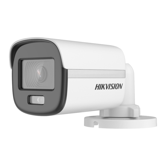
2 MP Full Time Color Camera
User Manual
Thank you for purchasing our product. If there are any
questions, or requests, do not hesitate to contact the
dealer.
This manual applies to the models below:
Type I Camera
Type II Camera
Type III Camera
Type IV Camera
Type V Camera
This manual may contain several technical mistakes or
printing errors, and the content is subject to change
without notice. The updates will be added to the new
version of this manual. We will readily improve or
update the products or procedures described in the
manual.
Type
User Manual
Model
DS-2CE10DF0T-F
DS-2CE10DF0T-PF
DS-2CE12DF0T-F
DS-2CE70DF0T-PF
DS-2CE70DF0T-MF
DS-2CE72DF0T-F
0104001091207
Advertisement
Table of Contents


Need help?
Do you have a question about the DS-2CE10DF0T-F and is the answer not in the manual?
Questions and answers