Table of Contents
Advertisement
Quick Links
Advertisement
Table of Contents

Related Manuals for Foxtech MK15


Summary of Contents for Foxtech MK15
- Page 1 MK15 Radio Controller User...
-
Page 2: Table Of Contents
Directory 1 MK15..................................1 ................ 1 Diagram of Remote Control Switch and Interface ....................2 Diagram of the Air Unit Interface 1.3 Switch button and channel ........................... 3 1.4 parameters ................................ 4 ..................... 6 1.5 Turn on/off the remote controller 1.6 Screenshot ................................ -
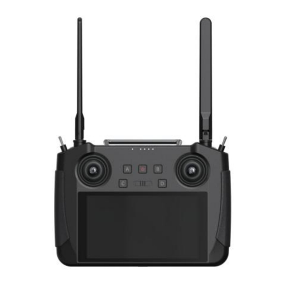
Page 3: Diagram Of Remote Control Switch And Interface
MK15 Diagram of Remote Control Switch and Interface... -
Page 4: Diagram Of The Air Unit Interface
user manual Diagram of the Air Unit Interface... -
Page 5: Switch Button And Channel
1.3 Switch,Button and Channel MK15 remote controller has 13 physical switches and 16 channel outputs MK15 remote control channel definition and switch distribution Channel Switch Name Default number physical switch Aileron Joystick Elevating Joystick (Mode II) Throttle Joystick (Mode II)... -
Page 6: Parameters
user manual The remote controller supports custom channel mapping, please refer to the " Tuning APP" chapter of this manual 1.4 Parameters... - Page 7 user manual...
-
Page 8: Turn On/Off The Remote Controller
1.7 Remote Controller Charging Please use the standard PD charger to charge the MK15 remote controller. After connecting the charging connector, the red light on the left side of the Type-c interface will light up to indicate that charging has started. After the charging is completed, the indicator light will turn green. -
Page 9: Reference Diagram For Antenna Installation And Use
user manual Reference diagram for antenna installation and use Diagram of the remote controller signal angle Using diagram of the remote controller antenna Using diagram of sky end antenna... -
Page 10: Remote Controller App
Antenna installation diagram for high-altitude flight. (If the flying altitude is more than 10 meters, the antenna facing downwards.) 2 Remote Controller APP The MK15 setting parameters are set through the built-in Tuning APP. 2.1 Channel setting Through the channel setting function, the user can... - Page 11 user manual actual PWM is 1950us. Neutral point adjustment Select the target channel and click to output the corresponding neutral point value.
-
Page 12: Data Link Setting
user manual Servo reverse Select the target channel and click the corresponding servo forward and reverse switch to successfully set the servo forward and reverse. Channel mapping The user can freely define the control switch of each channel from the default joystick, dial and buttons. -
Page 13: System Settings
user manual Baud rate selection If you are connected to other devices, you can change the flight controller to custom and manually select the corresponding baud rate to connect. 2.3 System Setting Adjust the system settings of the remote controller, such as remote control frequency pairing, changing the language, changing the throttle joystick etc. -
Page 14: Fail-Safe Protection
user manual 1. Click "Start pairing" in the APP, the LED status light will flash red light, and the APP will remind you "paring". 2.Click the receiver pairing button for 2 seconds, the red LED will flash quickly, and the paring will be successful. 3. - Page 15 user manual...
-
Page 16: Connect To The Ground Station Via Usb
user manual 3 Data link(Connect to GCS) Connect to the ground station via USB 1. Enter the Assistant APP, open the data link setting and change the connection mode to "USB serial port" connection. 2. Open the ground station APP and select USB connection (At this time, the APP will remind whether to allow the USB permission, please select OK). -
Page 17: Use A Ethernet Camera/Gimbal Camera/Camera
user manual 4 Video Link(FPV) Use a third-party FPV camera Open the FPV APP to display the image direcly. Use a Ethernet camera/gimbal camera/camera Because the air unit network segment is 192.168.144, please change the IP address to 192.168.144 before using the camera(It cannot be used without modification). 2. -
Page 18: Connection Method Of The Hdmi Version Camera
user manual 4.3 Connection Method of the HDMI Version Camera 1. Use the HDMI cable to connect the video device to the HDMI processing module, and connect the data output cable of the HDMI processing module to the air unit. 2. - Page 19 user manual 4.4 Parameter Air unit IP address: 192.168.144.11 Ground unit IP address: 192.168.144.12 Three proofings FPV camera address: 192.168.144.25 HDMI encoder address: 192.168.144.64 three proofings FPV camera RTSP address: rtsp://192.168.144.25:554/main.264 HDMI encoder RTSP address: rtsp://192.168.144.64:554/live/0 Commonly used video player software: QGroundControl, EasyPlayer Video playing URL: Because the video input device manufacturers are different, the URL will also be different, the actual address provided by the camera (in the camera's parameter setting page) Network diagnosis Android APP: Android version of ping tool...
Need help?
Do you have a question about the MK15 and is the answer not in the manual?
Questions and answers