Table of Contents
Advertisement
Quick Links
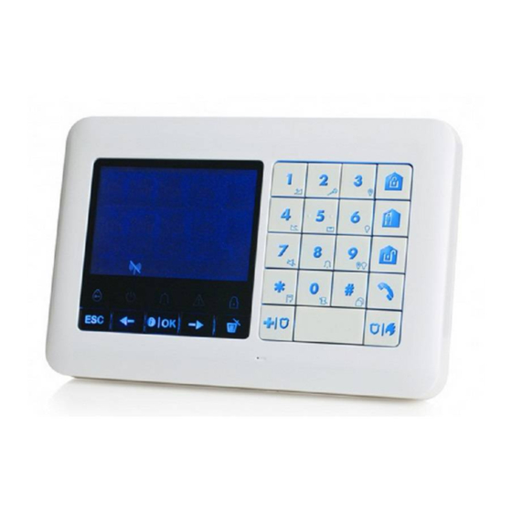
WK250
Advanced Two-Way Keypad
Table of Contents
1. Introduction ................................................................................................................................................................. 4
2. Installation .................................................................................................................................................................. 4
2.1 Inserting Battery ................................................................................................................................................ 4
2.2 Desktop Installation .......................................................................................................................................... 4
2.3 Wall Mounting ................................................................................................................................................... 5
2.4 Enrollment of the WK250 Keypad in WP8010/WP8030 .................................................................................... 6
2.5 Enrollment of the First WK250 Keypad in WP8033 .......................................................................................... 7
2.6 Configuring the WK250 Parameters ................................................................................................................. 8
3. Programming ............................................................................................................................................................ 10
3.1 General Guidance ........................................................................................................................................... 10
3.1.1 Navigation ................................................................................................................................................ 10
3.1.2 Feedback Sounds .................................................................................................................................... 10
3.2 Entering the "Installer Mode" and Selecting a Menu Option ........................................................................... 10
3.2.1 Entering the "Installer Mode" if "User Permit" is enabled ......................................................................... 12
3.2.2 Selecting options...................................................................................................................................... 12
3.2.3 Exiting the Installer Mode ......................................................................................................................... 12
3.3 Setting Installer Codes .................................................................................................................................... 12
3.3.1 Identical Installer and Master Installer Codes .......................................................................................... 14
3.4 Zones / Devices .............................................................................................................................................. 14
3.4.1 General Guidance & Zones/Devices Menu Options................................................................................. 14
3.4.2 Adding New Wireless Devices or Wired Sensors..................................................................................... 15
3.4.3 Deleting a Device ..................................................................................................................................... 20
3.4.4 Modifying or Reviewing a Device ............................................................................................................. 21
3.4.5 Replacing a Device .................................................................................................................................. 22
3.4.6 Configuring Soak Test Mode ................................................................................................................... 23
3.4.8 Updating Devices after Exiting Installer Mode ......................................................................................... 25
3.4.9 WK250 Display when WP Panel is Active ................................................................................................ 25
3.5 Control Panel .................................................................................................................................................. 26
3.5.1 General Guidance - "Control Panel" Flow-Chart & Menu Options ........................................................... 26
3.5.2 Configuring Arming/Disarming and Exit/Entry Procedures ....................................................................... 28
3.5.3 Configuring Zones Functionality............................................................................................................... 30
3.5.4 Configuring Alarms & Troubles ................................................................................................................ 31
Installer's Guide
Advertisement
Table of Contents

Related Manuals for Tyco DSC WK250


Summary of Contents for Tyco DSC WK250
-
Page 1: Table Of Contents
WK250 Advanced Two-Way Keypad Installer’s Guide Table of Contents 1. Introduction ................................. 4 2. Installation .................................. 4 2.1 Inserting Battery ..............................4 2.2 Desktop Installation ............................4 2.3 Wall Mounting ..............................5 2.4 Enrollment of the WK250 Keypad in WP8010/WP8030 ..................6 2.5 Enrollment of the First WK250 Keypad in WP8033 .................. - Page 2 3.5.5 Configuring Sirens Functionality.......................33 3.5.6 Configuring Audible & Visual User Interface ....................34 3.5.7 Configuring Jamming and Supervision (Missing device) ................36 3.5.8 Configuring Miscellaneous Features ......................37 3.6 Communication ............................... 37 3.6.1 General Guidance – "Communication" Flow-Chart & Menu Options ............37 3.6.2 Configuring PSTN (landline phone) Connection..................41 3.6.3 Configuring GSM-GPRS (IP) - SMS Cellular Connection ................42 3.6.4 Configuring Events Reporting to Monitoring Stations ................43 3.6.5 Configuring Events Reporting to Private Users ..................50...
- Page 3 3.14.5 CP01 Setup ............................74 3.14.6 DEFAULT Setup ............................ 75 4. Periodic Test by Installer Code ..........................77 4.1 General Guidance ............................77 4.2 Conducting a Periodic Test ..........................77 5. Handling System Troubles ............................81 6. Reading the Event Log ............................. 83 APPENDIX A: Specifications ............................
-
Page 4: Introduction
1. Introduction 1. Introduction WK250 is a 2-way wireless PowerG keypad display device for use with the WP8010, WP8030, or WP8033 control panel, version 18 and higher. Up to 10 WK250 keypads can be enrolled in the WP panel. The WP8010, WP8030 and WP8033 panels are highly advanced wireless alarm control panels produced by DSC. -
Page 5: Wall Mounting
2. Installation 2.3 Wall Mounting The WK250 is mounted as illustrated in the following drawing. 1. Drill 4 mounting holes 3. Line the two slots of the unit with the two hinges of the bracket, and then slide the unit downward on the bracket. 2. -
Page 6: Enrollment Of The Wk250 Keypad In Wp8010/Wp8030
2. Installation 2.4 Enrollment of the WK250 Keypad in WP8010/WP8030 Refer to section 5.4 of the WP8010/WP8030 Installer Guide and follow the procedure under the "02:ZONES/DEVICES" option of the Installer Menu. A flowchart of the procedure is provided below. Step Action LCD Display Enter the Installer Mode in the WP panel and select... -
Page 7: Enrollment Of The First Wk250 Keypad In Wp8033
2. Installation 2.5 Enrollment of the First WK250 Keypad in WP8033 The WP8033 is designed to operate wirelessly with the WK250 keypad installed anywhere within the protected premises. The first keypad is always enrolled as Keypad no. 1. Note: The enrollment procedure described here is for the first WK250 keypad only. The enrollment of additional keypads is performed by the first enrolled WK250 keypad (for instructions, see section 3.4.2). -
Page 8: Configuring The Wk250 Parameters
2. Installation 2.6 Configuring the WK250 Parameters Enter the “Kxx.DEV SETTINGS” main menu on the WK250 keypad immediately after enrollment or through the “MODIFY DEVICES” menu if performed at a later stage. Choose the number of the keypad device to configure and follow the configuration instructions for the WK250 keypad. - Page 9 2. Installation SCREEN SAVER Enables or disables the screen saver option. disable Options settings: disable and enable. Notes: 1) When "SCREEN SAVER" is configured as "enable", pressing any button on the WK250 device will return the device to normal display. 2) When "SCREEN SAVER"...
-
Page 10: Programming
3. Programming 3. Programming 3.1 General Guidance This chapter explains the Installer programming (configuration) options of your WK250 device and how to customize its operation to your particular needs end user requirements. The alarm system includes a partition feature. Partitioning allows you to have up to three independently controllable areas with different user codes assigned to each partition. - Page 11 3. Programming Step 1 Step 2 Step 3 Select "INSTALLER MODE" Enter Installer Code Select "Installer Menu" Option Option HH:MM READY 01:INSTALL CODES 02:ZONES/DEVICES INSTALLER 03:CONTROL PANEL MODE ENTER CODE: If the "Installer Mode" is 04:COMMUNICATION not shown, refer to section 3.2.1...
-
Page 12: Entering The "Installer Mode" If "User Permit" Is Enabled
3. Programming 3.2.1 Entering the "Installer Mode" if "User Permit" is enabled In certain countries the regulations may require user permission to make changes in the configuration of the panel. To comply with these regulations, the "Installer Mode" option can be accessed only via the "User Settings" menu. The Master user must first enter the "User Settings"... - Page 13 3. Programming The following actions can be performed only by using the Master Installer code: • Changing the Master Installer code. • Defining specific communication parameters – see "3:C.S REPORTING” in sections 3.6.1 and 3.6.4. • Resetting the WK250 parameters to the default parameters – see "09:FACTORY DEFLT" in section 3.11. Note: Not every system includes a Master Installer code feature.
-
Page 14: Identical Installer And Master Installer Codes
3. Programming 3.3.1 Identical Installer and Master Installer Codes In a 2-installer code system, the non-master installer may inadvertently change the Installer Code to that of the Master Installer Code. In this case, the panel will allow the change in order to prevent the non-master installer from realizing the discovery of the Master Installer's Code. -
Page 15: Adding New Wireless Devices Or Wired Sensors
3. Programming 3.4.2 Adding New Wireless Devices or Wired Sensors Part A - Enrollment To enroll and configure a device, follow the instructions in the following chart: Step 1 Step 2 Select "ADD NEW DEVICE" Enroll the device or Enter the Option device ID ... - Page 16 3. Programming How to check Panel Device compatibility Each PowerG device bears a 7-character Customer ID printed on the device sticker in the format: FFF-M:DDD, (for example, 868-0:012) where FFF is the frequency band and M:DDD is the variant code. For PowerG system devices compatibility, make sure the frequency band (FFF) and the variant code (M) of the devices match.
- Page 17 3. Programming Step 7 Step 8 Step 9 Select Partition options Enter Partitions Menu Enter Device Settings Menu ➯ ➯ Z10:PARTITIONS Z10:PARTITIONS Z10:DEV SETTINGS Step 11 Step 10 [10] Configure Device Parameters Continue or End ...
- Page 18 3. Programming - Configuring New Devices Device Configuration: To review or change the Device Configuration (settings), press the button, otherwise scroll to the next option – see [11]. [10] To configure the device parameters, refer to its corresponding device datasheet in the device Installation Instructions.
- Page 19 3. Programming Zone No. and Type Description Zxx: ZONE TYPE Similar to "Perimeter" zone, but is temporarily ignored by the alarm system during 7.Perim-Follow entry/exit delay periods. Usually used for sensors protecting the route between the entrance door and the control panel. Zxx: ZONE TYPE This zone type is active 24 hours, even when system is DISARMED.
-
Page 20: Deleting A Device
3. Programming 3.4.3 Deleting a Device Step 1 Step 2 Step 3 Select "DELETE DEVICES" Select the respective device Select exact device you wish Option Group to delete 02:ZONES/DEVICES CONTACT SENSORS DELETE DEVICES MOTION SENSORS Z01:Motion Sens ID No. -
Page 21: Modifying Or Reviewing A Device
3. Programming 3.4.4 Modifying or Reviewing a Device To Modify or Review the device parameters proceed as follows: Step 1 Step 2 Step 3 Select "MODIFY Select the respective Select exact device you DEVICES" Option device Group wish to modify ... -
Page 22: Replacing A Device
3. Programming 3.4.5 Replacing a Device Use this option to replace a faulty device that is enrolled in the system with another device of the same type number (i.e. same first 3 digit of the ID number – see section 3.4.2.A) while keeping the same configuration of the original device. There is no need to delete the faulty device or to reconfigure the new device. -
Page 23: Configuring Soak Test Mode
3. Programming 3.4.6 Configuring Soak Test Mode This option enables you to enter device zones into Soak Test mode. To Enable the Soak Test proceed as follows: Step 1 Step 2 Select "ADD TO SOAK TEST" Select the respective device Group Option ... -
Page 24: Defining Configuration Defaults For "Device Settings
3. Programming 3.4.7 Defining Configuration Defaults for "Device Settings" WK250 enables you to define the Default Parameters used during enrollment and to change them whenever you wish so that new devices enrolled into the system will be configured automatically with these default parameters without the need to modify the configuration of each new enrolled device. -
Page 25: Updating Devices After Exiting Installer Mode
3. Programming – Changing Defaults Enter the Installer Menu, select the "02.ZONES/DEVICES" option (see section 3.2) and then select the "DEFINE DEFAULTS" option. Select the respective Group of the device you wish to define its defaults. For example, "MOTION SENSORS". -
Page 26: Control Panel
3. Programming 3.5 Control Panel 3.5.1 General Guidance – "Control Panel" Flow-Chart & Menu Options The "CONTROL PANEL" menu enables you to configure and customize the operation of the alarm system. The "CONTROL PANEL" menu provides you with configurable parameters divided into several groups, each dealing with certain aspects of the system operations as follows (see detailed list in Step 2 of the chart below): Group Description of Group Features and Parameters... - Page 27 3. Programming Step 2 Select the "Control Panel" parameter you wish to configure and go to the indicated group section of the selected option. When done to step 2. Sirens Arming & Disarming Alarms & Troubles Zone Behavior See section 3.5.2 See section 3.5.3...
-
Page 28: Configuring Arming/Disarming And Exit/Entry Procedures
3. Programming Jamming and Miscellaneous User Interface Supervision See section 3.5.6 See section 3.5.7 See section 3.5.8 51:PIEZO BEEPS 61:JAM DETECT 75:CODE VERSION 52:TROUBLE BEEPS 62:MISSING REPRT 91:USER PERMIT 53:MEMORY PROMPT 63:NOT READY 92:BATTERY TYPE 54:LOW BAT ACK 64:MISS JAM/ALRM 93:SOAK PERIOD 55:BACK LIGHT... - Page 29 3. Programming 03:Option and default Configuration Instructions exit/entry doors without causing an alarm. Slow-rate warning beeps start sounding once the arming command has been given, until the last 10 seconds of the delay, during which the beeping rate increases. Options: 30 seconds; 60 seconds; 90 seconds; 120 seconds, 3 minutes and 4 minutes.
-
Page 30: Configuring Zones Functionality
3. Programming 03:Option and default Configuration Instructions Options: off and on. Note: To enable the reporting, you must configure the system to report "alrt" events to Private users (Latchkey belongs to the "alerts" group of events). Refer to section 3.6.5 "REPORTED EVENTS"... -
Page 31: Configuring Alarms & Troubles
3. Programming Option and default Configuration Instructions 2. It is recommended that crossed zones will be only zones used for detection of burglary i.e. "Zone Types": Entry/ Exit, Interior, Perimeter and Perimeter follower. 3. If a cross zone is in Soak Test mode, then each zone of this zone couple functions independently. - Page 32 3. Programming Option and default Configuration Instructions Options: after 5 minute, after 30 minute, after 60 minute or after 3 hours. Note: To comply with EN requirements, the time delay must not exceed 60 min. Define a specific time period that if 2 successive alarms occur, the second alarm will be 36:CONFIRM ALARM considered as a confirmed alarm, (see section 3.6.4 option 61).
-
Page 33: Configuring Sirens Functionality
3. Programming Option and default Configuration Instructions Options: in 00/30/60/90 seconds 3.5.5 Configuring Sirens Functionality The following table provides you with a detailed description of each option and its configuration settings. To select an option and change its configuration – refer to section 3.5.1. Option and default Configuration Instructions Determine whether the control panel’s built-in siren will sound alarms –... -
Page 34: Configuring Audible & Visual User Interface
3. Programming 3.5.6 Configuring Audible & Visual User Interface The following table provides you with a detailed description of each option and its configuration settings. To select an option and change its configuration – refer to section 3.5.1. Option and default Configuration Instructions Define whether the panel will sound the exit/entry warning beeps during exit and 51:PIEZO BEEPS... - Page 35 3. Programming Option and default Configuration Instructions Define whether the panel's back lighting will remain on at all times or will turn on 55:BACK LIGHT only when a key is pressed and turn off within 10 seconds if no further keystrokes OFF after 10sec are sensed.
-
Page 36: Configuring Jamming And Supervision (Missing Device)
3. Programming 3.5.7 Configuring Jamming and Supervision (Missing device) The following table provides you with a detailed description of each option and its Options. To select an option and change its setting (configuration) – refer to section 3.5.1. Option and default Configuration Instructions Define whether jamming (continuous interfering transmissions on the radio network) 61:JAM DETECT... -
Page 37: Configuring Miscellaneous Features
3. Programming 3.5.8 Configuring Miscellaneous Features The following table provides you with a detailed description of each option and its configuration settings. To select an option and change its configuration – refer to section 3.5.1. Option and default Configuration Instructions Define the WP code version (default "000") which needs to be synchronized with 75:CODE VERSION the monitoring station when the anti-code reset function is enabled (see menu... - Page 38 3. Programming Contains configurable features and parameters related to the Cellular 2:GSM/GPRS/SMS 3.6.3 connection of the WP system. Contains configurable features and parameters related to Reporting of 3:C.S.REPORTING 3.6.4 event messages to Monitoring Stations via telephone, cellular or IP broadband communication. Contains configurable features and parameters related to Reporting event 4:PRIVATE REPORT 3.6.5...
- Page 39 3. Programming Step 2 Step 3 Step 4 Select Communication Sub-menu Select the "Communication" Parameter you wish to configure SMS REPORT GPRS ALWAYS ON GPRS APN GSM KEEP ALIVE GPRS USERNAME TRANS PROTOCOL SIM PIN CODE 3.6.4 ...
- Page 40 3. Programming Step 2 Step 3 Step 4 Select Communication Sub-menu Select the "Communication" Parameter you wish to configure REPORTED EVENTS REPORTED EVENTS Private tel#1 SMS tel#1 See also Chapter 6, section Private tel#2 SMS tel#2 B.12, in the WK250 Private tel#3 SMS tel#3...
-
Page 41: Configuring Pstn (Landline Phone) Connection
3. Programming Step 2 Step 3 Step 4 Select Communication Sub-menu Select the "Communication" Parameter you wish to configure Mast. UL/DL codes 1st caller ID# Inst. UL/DL codes 2nd caller ID# UL/DL modes 7:BROADBAND 3.6.8 DHCP CLIENT MANUAL IP RESET MODULE 3.6.2 Configuring PSTN (landline phone) Connection... -
Page 42: Configuring Gsm-Gprs (Ip) - Sms Cellular Connection
3. Programming Enter "1:PSTN TEL LINE", select the menu you wish to configure (see guidance above and in section 3.6.1), then refer to the table below. Option and default Configuration Instructions AREA CODE SKIP In some older PSTN networks, it may not be possible to dial from the control panel to other PSTN telephone numbers (such as monitoring stations or private phones), if the dialed number contains an area code which is identical to the area code of the panel (i.e. -
Page 43: Configuring Events Reporting To Monitoring Stations
3. Programming disable via the SMS Channel. For further information, see section 3.6.4 options 26 & 27. Options: disable; enable. GPRS APN Enter the name of the APN Access Point used for the internet settings for the GPRS (up to 16 digits string). Note: To enter the APN Access Point, use the “String Editor”... - Page 44 3. Programming communications channels. In this section, you configure and define all parameters and features required for the reporting of the event messages to Monitoring Stations such as: • The events reported to each of the two Monitoring Stations C.S.1 and C.S.2 and corresponding backups. •...
- Page 45 3. Programming Option and default Configuration Instructions RCVR1 or RCV1) and a 2 Account (subscriber) number (12:RCVR 2 ACCOUNT) that will identify the system to the 2 Monitoring Station (designated as RCVR2 or 12:RCVR2 ACCOUNT RCV2). Each of the Account numbers consists of 6 hexadecimal digits. 005678 Master Installer only To enter Hexadecimal digits, use the following table:...
- Page 46 3. Programming Option and default Configuration Instructions SMS text format please contact DSC. 27:SMS RCVR2 Enter the two telephone numbers (including area code – maximum 16 digits).of the SMS Receiver 1 located at the 1 Monitoring Station (26:SMS RCVR 1) and SMS Master Installer only Receiver 2 located at the 2 Monitoring Station (27:SMS RCVR 2).
- Page 47 3. Programming Option and default Configuration Instructions 53:COM.FAIL RPRT Determine whether a failure in any of the system communication channels i.e. PSTN or GSM/GPRS will be reported or not and the time delay between detection of the failure and reporting of the failure event to the Monitoring Station. A trouble event (i.e. "tel line fail", "GSM line fail”...
- Page 48 3. Programming Option and default Configuration Instructions Monitoring Station (to turn the Monitoring Station from data communication to voice Send 2wv code communication state) by using pre-selected SIA or Contact-ID communication format disable only. voice c.s.: Select the timeout for 2-way voice communication with Monitoring voice<- ->cs Stations, or enable the Monitoring Station to ring back for 2-way voice function.
- Page 49 3. Programming Event Reporting Chart To simplify the configuration of reporting system events to Monitoring Stations, the event messages are divided into 5 Event Groups as described in the following table below: Due to lack of space in the display, the following abbreviations are used alrm, alrt, o/c”...
-
Page 50: Configuring Events Reporting To Private Users
3. Programming 3.6.5 Configuring Events Reporting to Private Users The WP system can be programmed to send various event notifications such as alarm, arming or trouble events, to 4 Private telephone subscribers using audible signals and if a GSM option is installed, the system can send the messages also to 4 SMS telephone numbers. -
Page 51: Configuring Upload / Download Remote Programming Access Permission
3. Programming Option and default Configuration Instructions arming modes (i.e. "Always") or restricted only to a specific limited time window that “VIEW TIME WINDOW” menu follows an alarm event. appears only if an option other than "disable" is selected in “VIEW ON DEMAND”... - Page 52 3. Programming Option and default Configuration Instructions Mast. UL/DL code Enter the 4-digit password (Master Installer download code) code that will allow the Master Installer to access the system remotely and upload/download data to the WP panel. Note: "0000" is not a valid code and must not be used. Inst.
-
Page 53: Broadband
3. Programming 3.6.8 Broadband Note: If the Broadband Module is not registered to the WP, the menu "7:BROADBAND" will not be displayed on the WK250. In this section you can configure how to obtain an IP address, enter LAN parameters and reset broadband module settings. -
Page 54: Pgm Output
3. Programming 3.7 PGM Output 3.7.1 General Guidance The "05:OUTPUTS" menu enables you to select events/conditions under which the PGM (programmable) output will function and to select the internal sounder or STROBE light (that will be activated according to system programming). - Page 55 3. Programming PGM: BY SENSOR Activates the PGM output upon activation of any one of up to 3 sensors (zones) in the systems irrespective of whether the system is armed or disarmed. To configure: Zone A Z:_ _ Press to enter the "PGM: BY SENSOR" sub menu and then select the Zone you wish to program, for example "Zone A".
-
Page 56: Pgm-5 Connection
3. Programming 3.7.4 PGM-5 Connection ⋅⋅⋅ 05:OUTPUS EXTERNAL PGM PGM-5 OPTIONS If a PGM-5 module has been connected, proceed to enable the operation of the module as follows: Step 1 Step 3 Step 2 Select "EXTERNAL PGM" menu Select "05:OUTPUTS" menu Press ... -
Page 57: Custom Names
3. Programming 3.8 Custom Names 3.8.1 Custom Zone Names During the device enrollment process you also define the Location name where the device is installed. The location name is selected from a location list of Custom names - see Section 3.4.2, Part B, for Location List and instructions. Define the custom location names according to your specific needs and use them during the device enrollment. - Page 58 3. Programming WK250 String Editor Note: The icons and numbers shown on the above keypad drawing are for illustrative purposes only. String Editor Functionality String Editor Functionality Short press: toggles between Insert and overwrite. ' ', '0' Long press: Changes between lowercase letters (a,b,c…z) and uppercase letters (A,B,C…Z).
-
Page 59: Record Speech
3. Programming 3.8.2 Record Speech You can record short-duration speech messages for the house identity, user names and custom zone names. For the recording procedure follow the instructions below. Additional details and guidance are provided in section 3.2. ⋅⋅⋅ 06:CUSTOM NAMES RECORD HOUSE ID Enter "RECORD SPEECH", select the menu you wish to perform (see guidance above), and then refer to the tables below which provide you with detailed explanations for each option. -
Page 60: Voice Box Mode
3. Programming Option Instructions VOICE LOC.#1 You can record zone names (for example, Garage door, Guest room, etc.), and assign Dining room them to specific zones. When done, press to return. Press to select the zone name you wish to record, for example "VOICE LOC. #01"... - Page 61 3. Programming 3.9.2 WL DEVICES Describes how to test the devices attached to the WP panel, review devices' status and RF signal status. You can test all devices, test single device, review devices status and review RF problems, in case of any. 3.9.3 GSM/GPRS Describes how to test the GSM/GPRS/SIM communication module.
-
Page 62: Testing Wireless Devices
3. Programming Step 2 Step 3 SIM NUMBER TEST SIM# verified Tst by IP RCVR 1 Tst by IP RCVR 2 BROADBAND MODULE Unit is OK PLEASE WAIT… 3.9.2 Testing Wireless Devices The WP enables you to test the wireless devices attached to the panel. You can test all devices, one device at a time, display devices' status and review RF problems, in case of any. - Page 63 3. Programming Option Instructions While in the panic button test process, indicated by the corresponding display, for example, "TEST PANIC BT: XX", press a button on the pendant. TEST ONE DEVICE You can select a specific device group you wish to test, for example, Motion Sensors.
-
Page 64: Testing The Gsm Module
3. Programming Option Instructions SHOW RF PROBLEMS You can view only the devices which have RF problems. Note: This option is available only after testing process was done. Press to view the devices' status. The following screen will appear: "Zxx: 24hr: <status>" "Zxx: NOW: <status>"... -
Page 65: Testing The Sim Number
3. Programming Message Description APN not defined APN is not configured. SIM card locked After entering a wrong PIN code 3 consecutive times the SIM is locked. To unlock it enter a PUK number. The PUK number cannot be entered by the control panel. PowerManage denies the connection request. -
Page 66: User Settings
3. Programming Message Description BROADBAND MODULE The Ethernet cable is not connected to the Broadband Module. CABLE UNPLUGGED BROADBAND MODULE This message appears in any of the following cases: Check lan config • Incorrect Broadband Module IP has been entered. •... - Page 67 3. Programming Step 1 Step 2 Select "leave KP250" or "del all Enter “09:FACTORY DEFLT” menu devices" 09:FACTORY DEFLT 09:FACTORY DEFLT leave KP250 or 09:FACTORY DEFLT del all devices Step 3 Step 4 Enter the Installer Code Press <OK>...
-
Page 68: Serial Number
3. Programming 3.12 Serial Number The SERIAL NUMBER menu enables reading the system serial number and similar data for both WP control panel and WK250 keypad for support purposes only. To read the system serial number and other relevant data proceed as follows: Step 1 Step 2... -
Page 69: Enabling / Disabling Partitions
3. Programming 3.13.2 Enabling / Disabling Partitions To enable or disable the partition feature, proceed as follows: Step 3 Step 1 Step 2 Select whether to "Enable" or Select "12:PARTITIONING" menu "Disable" Partitions Partitions are now enabled 12:PARTITIONING 12:PARTITIONING 12:PARTITIONING disable... -
Page 70: Bs8243 Setup
3. Programming 3.14.3 BS8243 Setup ⋅⋅⋅ 13:OPERATION MOD 02:BS8243 SETUP Enter the "02:BS8243 SETUP " menu, and press to configure its settings. Option and default Configuration Instructions 01:DISARM OPTION Define when it is possible to disarm the system: entry/BS devs entry/BS devs –... - Page 71 3. Programming 05:CONFIRM ALARM Define a specific time period that if 2 successive alarms occur, the second alarm will be in 30 minutes considered as a confirmed alarm, (see RPT CNFM ALRM below). Options: in 30/45/60/90 minutes 06:CONFIRM PANIC A confirmed panic alarm is reported if one of the following occurs within the confirmation in 20 hours time: a) A second panic device is activated.
-
Page 72: Dd243 Setup
3. Programming 3.14.4 DD243 Setup ⋅⋅⋅ 13:OPERATION MOD 03:DD243 SETUP Enter the "03:DD243 SETUP" menu, and press to configure its settings. Option and default Configuration Instructions 01:DISARM OPTION Define when it is possible to disarm the system: entry/DD devs entry/DD devs - During entry delay, when the system is armed AWAY, by using the keyfob or keyprox. - Page 73 3. Programming Option and default Configuration Instructions 06:CONFIRM PANIC A confirmed panic alarm is reported if one of the following occurs within the in 20 hours confirmation time: a) A second panic device is activated. b) A second panic alarm on the same device is activated. A tamper event is activated (not from the zone / device that initiated the panic alarm).
-
Page 74: Cp01 Setup
3. Programming 3.14.5 CP01 Setup ⋅⋅⋅ 13:OPERATION MOD 04:CP01 SETUP Enter the "04:CP01 SETUP" menu, and press to configure its settings. Option and default Configuration Instructions Certain regulations require that when the system is armed in AWAY mode, it may 01:DISARM OPTION not be disarmed from the outside of the house (such as by keyfobs) before any time... -
Page 75: Default Setup
3. Programming Option and default Configuration Instructions Slow-rate warning beeps start sounding once the door is opened, until the last 10 09:ENTRY DELAY 2 seconds of the delay, during which the beeping rate increases. Locations No. 1 (entry 30 seconds delay 1) and 2 (entry delay 2) allow you to program the length of these delays. - Page 76 3. Programming Option and default Configuration Instructions The "Exit Delay" time can be further adjusted according to your preferred exit route. 03:END EXIT MODE The WK250 provides you with the following "Exit Mode" options: normal normal – The exit delay is exactly as defined. restart>reentry - Exit delay restarts when the door is reopened during exit delay.
-
Page 77: Periodic Test By Installer Code
4. Periodic Test by Installer Code 4. Periodic Test by Installer Code 4.1 General Guidance This mode provides you with the means to conduct a periodic test, via the "PERIODIC TEST" menu, at least once a week and after an alarm event. When you are instructed to perform a periodic test, walk throughout the site to check the detectors / sensors (except for Sirens and Temperature Sensors). - Page 78 4. Periodic Test by Installer Code Option Instructions SIRENS TEST You can test wireless sirens and strobes and sirens of smoke sensors and keypads. To initiate the siren test press . The display now reads "SIREN N" “<NEXT> or <OK>”.
- Page 79 4. Periodic Test by Installer Code Option Instructions TEST ONE DEVICE Select a specific device group you wish to test. For example, Motion Sensors. Press to enter the "TEST ONE DEVICE" sub menu and use to scroll through the device families. Press to enter the <...
- Page 80 4. Periodic Test by Installer Code Option Instructions Press to enter the "TEST ONE DEVICE" sub menu and use navigate to "SHOCK SENSORS". Press ; the following screens will appear: "Zxx:Shk+AX+CntG3" <location>. Press continuously to select a different zone number. ;...
-
Page 81: Handling System Troubles
5. Handling System Troubles 5. Handling System Troubles Fault What it means Solution The control panel cannot configure or Make sure the device is physically control the device. present. 1-WAY Battery consumption increases. Check the display for device faults, for example, low battery. Use RF diagnostics to check the current signal strength and during the last 24 hours. - Page 82 5. Handling System Troubles Fault What it means Solution Enter and exit the installer menu Disconnect GSM unit and install it again Replace SIM card Replace the GSM unit A radio-frequency signal which is Locate the source of interference by blocking communication channel of switching off any wireless devices SYSTEM JAMM...
-
Page 83: Reading The Event Log
6. Reading the Event Log Fault What it means Solution TROUBLE Detector alarms when in Soak Test If you wish to continue the Soak Test, mode no further action should be taken. SOAK TEST FAIL If you wish to abort the Soak Test, disable the Soak Test (see section 3.4.6). - Page 84 6. Reading the Event Log While the system is in the normal operating mode, press the key. Reading the Event Log Enter the current Installer Code and then press to enter "LIST OF EVENTS". The latest event is shown. The event is displayed in two parts, for example, "Z13 alarm" and "09/02/10 3:37 P". Press repeatedly to scroll through the list of events.
-
Page 85: Appendix A: Specifications
APPENDIX A: Specifications APPENDIX A: Specifications Frequency Band (MHz) Europe and rest of world: 433-434, 868-869 USA: 912-919 Communication Protocol PowerG Battery type Four 1.5V AA Alkaline batteries Battery Life Expectancy 3 years (for typical use). Low Battery Threshold 3.8 V Power source Battery: 4.8VDC –... -
Page 86: Appendix B: Working With Partitions
APPENDIX B: Working with Partitions APPENDIX B: Working with Partitions Your alarm system is equipped with an integrated partitioning feature that can divide your alarm system into three distinct areas identified as Partition 1 through 3. A partition can be armed or disarmed regardless of the status of the other partitions within the system. - Page 87 APPENDIX B: Working with Partitions Common area zone types Definition Gas; Temperature; 24-hour silent; 24-hour audible; Non- alarm Note: A Soak Test of Common areas cannot be initiated when one of its partitions is armed. When Soak Test of a Common area is active, an alarm event is ignored unless all the partitions that are assigned to the zone are armed.
-
Page 88: Appendix C: Glossary
APPENDIX C: Glossary APPENDIX C: Glossary Abort Period: When an alarm is initiated, the internal sounder is activated first for a limited period of time which is the abort period set by the installer. If you cause an alarm accidentally, you can disarm the system within the abort period before the real sirens start and before the alarm is reported to the remote responders. - Page 89 APPENDIX C: Glossary HOME: This type of arming is used when people are present within the protected site. A classic example is night-time at home, when the family is about to retire to bed. With HOME arming, perimeter zones are protected but interior zones are not.
- Page 90 APPENDIX C: Glossary alarm system. Zone: A zone is an area within the protected site under supervision of a specific detector. During programming, the installer allows the control panel to learn the detector’s identity code and links it to the desired zone. Since the zone is distinguished by number and name, the control panel can report the zone status to the user and register in its memory all the events reported by the zone detector.
-
Page 91: Appendix D: Compliance With Standards
APPENDIX D: Compliance with Standards APPENDIX D: Compliance with Standards Designed to comply with Standards Europe: EN 300220-1, EN 300220-2, EN300330, EN301489, EN60950, EN50131-1, EN50131-3, EN50131-6. The WK250 is compatible with the RTTE requirements - Directive 1999/5/EC of the European Parliament and of the Council of 9 March 1999 and EN50131-1 Grade 2 Class II. - Page 92 (ii) products which are not identified with DSC's product product will be charged for each replacement unit. label and lot number or serial number; ©2016 Tyco International Ltd. and its Respective Companies. All Rights Reserved. Toronto, Canada www.dsc.com Printed in Israel WK250 Installer’s Guide, D-306488...
Need help?
Do you have a question about the DSC WK250 and is the answer not in the manual?
Questions and answers