U-Line 1215BEV User Manual & Service Manual
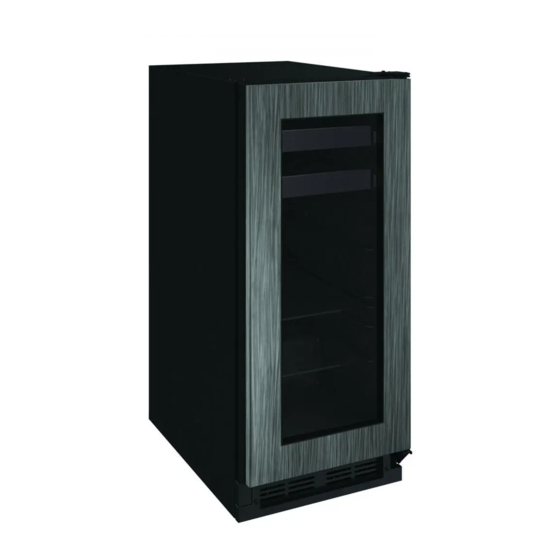
15" beverage center
Hide thumbs
Also See for 1215BEV:
- User manual & service manual (70 pages) ,
- User manual & service manual (60 pages)
Table of Contents
Troubleshooting

Related Manuals for U-Line 1215BEV


Summary of Contents for U-Line 1215BEV
- Page 1 USER GUIDE & SERVICE MANUAL SAFETY • INSTALLATION & INTEGRATION • OPERATING INSTRUCTIONS • MAINTENANCE • SERVICE RIGHT PRODUCT. RIGHT PLACE. RIGHT TEMPERATURE. SINCE 1962. 1000 Series 1215BEV 15" BEVERAGE CENTER • •...
-
Page 2: Table Of Contents
Grille / Plinth Installation Compressor Specifications Door Swing Troubleshooting Extended Door Stop Control Quick Guide Door Adjust Thermistor Wood Trim Finishing Defrost Operating Instructions First Use Control Operation Sabbath Mode Airflow and Product Loading U-Line Wine Guide Recommended Wine Storage Interior Shelves... - Page 3 1. U-Line Customer Care must be contacted immediately at +1.800.779.2547. 2. Service or repairs performed on the unit without prior written approval from U-Line is not permitted. If the unit has been altered or repaired in the field without prior written approval from U-Line, claims will not be eligible.
-
Page 4: Safety And Warning
USER GUIDE u-line.com SAFETY • INSTALLATION & INTEGRATION • OPERATING INSTRUCTIONS • MAINTENANCE • SERVICE Safety and Warning DANGER NOTICE This unit contains R600a (Isobutane) which is a Please read all instructions before installing, flammable hydrocarbon. It is safe for regular operating, or servicing the appliance. -
Page 5: Disposal And Recycling
USER GUIDE u-line.com SAFETY • INSTALLATION & INTEGRATION • OPERATING INSTRUCTIONS • MAINTENANCE • SERVICE Disposal and Recycling DANGER RISK OF CHILD ENTRAPMENT. Before you throw away your old refrigerator or freezer, take off the doors and leave shelves in place so children may not easily climb inside. -
Page 6: Environmental Requirements
USER GUIDE u-line.com SAFETY • INSTALLATION & INTEGRATION • OPERATING INSTRUCTIONS • MAINTENANCE • SERVICE Environmental Requirements This model is intended for indoor/interior applications only and is not to be used in installations that are open/ exposed to natural elements. - Page 7 USER GUIDE u-line.com SAFETY • INSTALLATION & INTEGRATION • OPERATING INSTRUCTIONS • MAINTENANCE • SERVICE Electrical WARNING SHOCK HAZARD — Electrical Grounding Required. Never attempt to repair or perform maintenance on the unit until the electricity has been disconnected. Never remove the round grounding prong from the plug and never use a two-prong grounding adapter.
-
Page 8: Cutout Dimensions
SAFETY • INSTALLATION & INTEGRATION • OPERATING INSTRUCTIONS • MAINTENANCE • SERVICE Cutout Dimensions PREPARE SITE Your U-Line product has been designed for either free- standing or built-in installation. When built-in, your unit does not require additional air space for top, sides, or rear. -
Page 9: Product Dimensions
USER GUIDE u-line.com SAFETY • INSTALLATION & INTEGRATION • OPERATING INSTRUCTIONS • MAINTENANCE • SERVICE Product Dimensions 23-1/4" (591 mm) (Includes 3/4" [20 mm] Integrated Panel) 34-1/8" to 35-1/8" (867 mm to 892 mm) 3-9/16" (91 mm) 14-15/16" (379 mm) -
Page 10: Side By Side Installation
USER GUIDE u-line.com SAFETY • INSTALLATION & INTEGRATION • OPERATING INSTRUCTIONS • MAINTENANCE • SERVICE Side-by-Side Installation 3. Place bracket over holes and attach to unit with two screws removed in step 2 using a T-25 Torx driver. Two units may be installed side-by-side. -
Page 11: Anti-Tip Bracket
USER GUIDE u-line.com SAFETY • INSTALLATION & INTEGRATION • OPERATING INSTRUCTIONS • MAINTENANCE • SERVICE Anti-Tip Bracket FLOOR MOUNTED ANTI-TIP INSTALLATION 1. Locate two anti-tip brackets included in the kit. 1. Slide unit out so screws on top of unit are easily accessible. - Page 12 USER GUIDE u-line.com SAFETY • INSTALLATION & INTEGRATION • OPERATING INSTRUCTIONS • MAINTENANCE • SERVICE 4. Remove the unit. Using a square, extend center line 5. Place the anti-tip brackets on the floor against the line “B” (see chart below). This line serves as the back drawn for the outer edge.
-
Page 13: General Installation
USER GUIDE u-line.com SAFETY • INSTALLATION & INTEGRATION • OPERATING INSTRUCTIONS • MAINTENANCE • SERVICE General Installation INSTALLATION 1. Plug in the power/electrical cord. LEVELING INFORMATION 1. Use a level to 2. Gently push the unit into position. Be careful not to confirm the unit is entangle the cord. -
Page 14: Integrated Panel Dimensions
USER GUIDE u-line.com SAFETY • INSTALLATION & INTEGRATION • OPERATING INSTRUCTIONS • MAINTENANCE • SERVICE Integrated Panel Dimensions Integrated Panel Dimensions INTEGRATED PANEL BACK SURFACE MUST HAVE AMPLE FLAT SURFACE TO MOUNT OVERLAY PANEL FLAT AND WITHOUT 3/4" INTERFERENCE (20 mm) NOTICE 14-3/4"... -
Page 15: Integrated Panel Installation
Integrated Panel Installation 6. Secure integrated panel to door/drawer Clamp 1. Fully open door/drawer. using clamps. A robust tape may also be used. U-Line 2. Starting at corner, pull recommends the use gasket away from door/ of bar clamps to drawer. Door/Drawer secure the panel to the door/drawer. - Page 16 USER GUIDE u-line.com SAFETY • INSTALLATION & INTEGRATION • OPERATING INSTRUCTIONS • MAINTENANCE • SERVICE 11.Remove clamps from door/drawer. NOTICE If panel requires additional adjustment after removing clamps, slightly loosen each screw and adjust panel as necessary. Tighten screws upon completion.
-
Page 17: Grille / Plinth Installation
USER GUIDE u-line.com SAFETY • INSTALLATION & INTEGRATION • OPERATING INSTRUCTIONS • MAINTENANCE • SERVICE Grille - Plinth Installation REMOVING AND INSTALLING GRILLE WARNING Disconnect electric power to the unit before removing the grille. When using the unit, the grille (plinth strip/base fascia) must be installed. -
Page 18: Door Swing
USER GUIDE u-line.com SAFETY • INSTALLATION & INTEGRATION • OPERATING INSTRUCTIONS • MAINTENANCE • SERVICE Door Swing Wall Wall 1/4" Min. 2-1/8" Min. (6 mm) (54 mm) Door Swing Door Swing Units have a zero clearance for the door to open 90°, when installed adjacent to cabinets. -
Page 19: Door Stop
3. On 24" models, a second pin is included for the bottom hinge. Repeat steps above for second hinge. Your U-Line unit was shipped to you with the optional 90° pin(s). (Models that are 15" wide include 1 pin. Models NOTE: Threaded pin will be inserted from the bottom. -
Page 20: Door Adjust
USER GUIDE u-line.com SAFETY • INSTALLATION & INTEGRATION • OPERATING INSTRUCTIONS • MAINTENANCE • SERVICE Door Adjustments DOOR ALIGNMENT AND ADJUSTMENT Align and adjust the door if it is not level or is not sealing properly. If the door is not sealed, the unit may not cool properly, or excessive frost may form in the interior. - Page 21 USER GUIDE u-line.com SAFETY • INSTALLATION & INTEGRATION • OPERATING INSTRUCTIONS • MAINTENANCE • SERVICE 3. Remove door by tilting forward and lifting door off 2. Remove magnet assembly from door with T-10 TORX bottom hinge. Retain shoulder washers; they will be driver.
- Page 22 USER GUIDE u-line.com SAFETY • INSTALLATION & INTEGRATION • OPERATING INSTRUCTIONS • MAINTENANCE • SERVICE SHIFTING WINE RACK SPACERS (OPTIONAL) 5. Place the spacer in between the liner and slide. NOTICE Only perform these steps if you require wine rack clearance with a 90° door opening. Doors which are allowed to open past 90°...
-
Page 23: Wood Trim Finishing
Not following this warning may cause the inner liner of the unit to have a permanent odor, which the warranty will not cover. ® U-Line recommends Minwax Brand Water Based Stains ® and Minwax Polycrylic Protective Finish. -
Page 24: First Use
USER GUIDE u-line.com SAFETY • INSTALLATION & INTEGRATION • OPERATING INSTRUCTIONS • MAINTENANCE • SERVICE First Use All U-Line controls are preset at the factory. Initial startup requires no adjustments. NOTICE U-Line recommends allowing the unit to run overnight before loading with product. As warm... -
Page 25: Control Operation
USER GUIDE u-line.com SAFETY • INSTALLATION & INTEGRATION • OPERATING INSTRUCTIONS • MAINTENANCE • SERVICE Control Operation CONTROL FUNCTION GUIDE FUNCTION COMMAND DISPLAY/OPTIONS ON/OFF Press and release Unit will immediately turn ON or OFF. Press and release to leave interior Toggle lights Glass door wine and beverage centers only. -
Page 26: Sabbath Mode
The unit will still maintain internal temperatures and set points. View a full list of Star-K certified U-Line units at www.star-k.org. To enable Sabbath Mode: 1. Press (4) and hold for ten seconds and release (the °F/°C symbol will flash briefly at the end of the ten... -
Page 27: Airflow And Product Loading
Anything in direct contact with the evaporator is subject to freezing. When properly loaded, your U-Line unit will store up to 60 (12 oz. [330 ml]) cans or 48 (12 oz. [330 ml]) bottles and 8 (750 ml) bottles of wine. -
Page 28: U-Line Wine Guide
YOUNG wine OLD wine LIGHT-BODIED wine FULL-BODIED wine Any step back in quality will be noticed. If a fine wine is tasted prior to a lesser wine, many of the fine wine’s subtle qualities may be missed. U-Line Wine Guide 1... - Page 29 Great Bordeaux’s may have as much as a 10-year plateau before fading. Myth 4: Wine color does not change with aging. Truth: As red wines age they get lighter in color while whites get darker. U-Line Wine Guide 2...
- Page 30 Wines can become flat or tired when voids and vacuums are created inside the wine bottle. In order to create voids and vacuums within a liquid, aggressive motion or shaking of the wine bottle would have to occur. U-Line Wine Guide 3...
- Page 31 Approximately 45°F (7°C) Sparkling ® Wine Captain Models - A Touch of Elegance In 1985 U-Line was the first North American appliance manufacturer to develop a residential wine storage unit, ® ® the Wine Captain . Each U-Line Wine Captain...
-
Page 32: Recommended Wine Storage
Specially designed horizontal wine racks properly position the bottles so the wine remains in contact with the cork, which ensures the cork does not become dry. U-Line recommends arranging wine bottles as shown in the illustrations below. Racks 1 and 2: NOTE: After stocking, allow unit to stabilize product temperatures for 24 hours. -
Page 33: Interior Shelves
USER GUIDE u-line.com SAFETY • INSTALLATION & INTEGRATION • OPERATING INSTRUCTIONS • MAINTENANCE • SERVICE Interior Shelves REMOVING AND INSTALLING INTERIOR SHELVES For models equipped with glass shelves having shelf supports, remove the shelves as follows: 1. Open door completely. -
Page 34: Maintenance
USER GUIDE u-line.com SAFETY • INSTALLATION & INTEGRATION • OPERATING INSTRUCTIONS • • SERVICE MAINTENANCE Cleaning If any surface discoloring or rusting appears, clean it ® ® quickly with Bon-Ami or Barkeepers Friend Cleanser EXTERIOR CLEANING and a nonabrasive cloth. Always clean with the grain. - Page 35 USER GUIDE u-line.com SAFETY • INSTALLATION & INTEGRATION • OPERATING INSTRUCTIONS • • SERVICE MAINTENANCE High ambient temperature and excessive humidity can also produce frost. CAUTION DO NOT use an ice pick or other sharp instrument to help speed up defrosting. These instruments can puncture the inner lining or damage the cooling unit.
-
Page 36: Cleaning Condenser
USER GUIDE u-line.com SAFETY • INSTALLATION & INTEGRATION • OPERATING INSTRUCTIONS • MAINTENANCE • SERVICE Cleaning Condenser INTERVAL - EVERY SIX MONTHS To maintain operational efficiency, keep the front grille free of dust and lint, and clean the condenser when necessary. -
Page 37: Wine Rack Installation
USER GUIDE u-line.com SAFETY • INSTALLATION & INTEGRATION • OPERATING INSTRUCTIONS • MAINTENANCE • SERVICE Wine Rack Installation To remove rack from the cabinet: 1. Remove any bottles stored on the rack. 2. Grasp the end of the rack and gently slide it out until it stops. -
Page 38: Extended Non-Use
If the unit will be exposed to temperatures of 40°F (5°C) or less, the steps above must be followed. For questions regarding winterization, please call U-Line at +1.800.779.2547. CAUTION Damage caused by freezing temperatures is not covered by the warranty. -
Page 39: Troubleshooting
• Evaporator: Refrigerant flowing through an evaporator may sound like boiling liquid. BEFORE CALLING FOR SERVICE If you think your U-Line product is malfunctioning, read • Condenser Fan: Air moving through a condenser may the CONTROL OPERATION section to clearly understand be heard. - Page 40 USER GUIDE u-line.com SAFETY • INSTALLATION & INTEGRATION • OPERATING INSTRUCTIONS • MAINTENANCE • SERVICE 6. After 24 hours, check the temperature of the water. If Problem Possible Cause and Remedy required, adjust the temperature control in a small Product Is Because product in contact with the rear wall increment (see CONTROL OPERATION).
-
Page 41: Warranty 1
One Year Limited Warranty For one year from the date of original purchase, this U-Line product warranty covers all parts and labor to repair or replace any part of the product that proves to be defective in materials or workmanship. For products installed and used for normal residential use, material cosmetic defects are included in this warranty, with coverage limited to 60 days from the date of original purchase. -
Page 42: Wire Diagram
USER GUIDE u-line.com SAFETY • INSTALLATION & INTEGRATION • OPERATING INSTRUCTIONS • MAINTENANCE • SERVICE Wire Diagram Wire Diagram 1... -
Page 43: Product Liability
The part that caused the damage must be returned to U-Line in its entirety. The part must be clearly labeled with the serial number of the unit it was removed from, the date, and the servicer who removed the part. -
Page 44: Warranty Claims
USER GUIDE u-line.com SAFETY • INSTALLATION & INTEGRATION • OPERATING INSTRUCTIONS • MAINTENANCE • SERVICE Warranty Claims warranty status. We also accept the following information to verify warranty status: The following information defines the parameters for filing a warranty claim: •... -
Page 45: Parts
Parts U-1215BEVINT-60A Item Description U-Line P/N Anti tip bracket w/screws 80-54221-00 Back panel 80-54392-00 Compressor electricals only 80-54149-00 Compressor w/electricals 80-54150-00 Condenser assembly 80-54231-00 Condenser fan w/screws 80-54014-00 Control Housing 80-54265-00 Display module 80-54252-00 Door assembly w/hinges 80-54791-00 10 Drain pan w/double sided tape... -
Page 46: Ordering Replacement Parts
Warranty parts will be shipped at no charge after U-Line confirms warranty status. Please provide the model, serial number, part number and part description. Some parts will require color or voltage information. -
Page 47: System Diagnosis Guide
USER GUIDE u-line.com SAFETY • INSTALLATION & INTEGRATION • OPERATING INSTRUCTIONS • MAINTENANCE • SERVICE System Diagnosis Guide REFRIGERATION SYSTEM DIAGNOSIS GUIDE System Suction Suction Compressor Condenser Capillary Evaporator Wattage Condition Pressure Line Discharge Tube Normal Normal Slightly below Very hot... -
Page 48: Compressor Specifications
USER GUIDE u-line.com SAFETY • INSTALLATION & INTEGRATION • OPERATING INSTRUCTIONS • MAINTENANCE • SERVICE Compressor Specifications OVERLOAD PROTECTOR STARTING RELAY DANGER Electrocution can cause death or serious injury. Burns from hot or cold surfaces can cause serious injury. Take precautions when servicing... -
Page 49: Troubleshooting Extended
Included in this section are some diagnostic tips and of Solenoid Valves: An occasional clicking sound may be course, if additional help is required please contact the heard as solenoid valves are operated. U-Line Corp, “Customer Care Facility” at +1.800.779.2547 for assistance. Troubleshooting - Extended 1... - Page 50 USER GUIDE u-line.com SAFETY • INSTALLATION & INTEGRATION • OPERATING INSTRUCTIONS • MAINTENANCE • SERVICE TROUBLESHOOTING GUIDE Concern Potential Causes Suggested Remedy Not Cooling Compressor overheating Verify proper air flow through condenser. Is condenser clean? Confirm condenser fan operation. Confirm proper compressor operating voltage. Use #19, Component Testing in Service Mode.
- Page 51 USER GUIDE u-line.com SAFETY • INSTALLATION & INTEGRATION • OPERATING INSTRUCTIONS • MAINTENANCE • SERVICE MAIN CONTROL Testing The Main Control The main control board is very robust and is rarely the If the main control is suspected of being faulty, the cause of system issues.
- Page 52 USER GUIDE u-line.com SAFETY • INSTALLATION & INTEGRATION • OPERATING INSTRUCTIONS • MAINTENANCE • SERVICE REED SWITCH A reed switch is used to monitor door state. When the door is closed magnetic force pulls the reed to its contact and closes the circuit which turns the light and display off.
- Page 53 USER GUIDE u-line.com SAFETY • INSTALLATION & INTEGRATION • OPERATING INSTRUCTIONS • MAINTENANCE • SERVICE Control Operation - Service UI BUTTON LAYOUT Hidden Button -Accesses Service Menu -No LED directly above. All LEDs turn on with button activation except #7.
- Page 54 USER GUIDE u-line.com SAFETY • INSTALLATION & INTEGRATION • OPERATING INSTRUCTIONS • MAINTENANCE • SERVICE CONTROL FUNCTION QUICK GUIDE FUNCTION COMMAND DISPLAY/OPTIONS ON/OFF Press and release Unit will immediately turn ON or OFF Press and release to leave interior light...
- Page 55 USER GUIDE u-line.com SAFETY • INSTALLATION & INTEGRATION • OPERATING INSTRUCTIONS • MAINTENANCE • SERVICE SERVICE MODE GUIDE SERVICE MODE GUIDE 1. THERMISTOR 1 — ZONE Service Mode Menu Item This shows the pure thermistor reading with no View thermistor #1 (no offsets) offsets taken into account.
- Page 56 USER GUIDE u-line.com SAFETY • INSTALLATION & INTEGRATION • OPERATING INSTRUCTIONS • MAINTENANCE • SERVICE 14. VIEW ERROR LOG 21. LIGHT ALL LED SEGMENTS A list of the errors in the order they occurred will This will illuminate all the LEDs on the display to scroll once on the display.
- Page 57 MODEL NUMBER 1. Disconnect the unit from power source. 2. Push and hold the U-Line button. 3. While still holding the U-Line button, plug the unit into the appropriate power source. 4. When the flashing digits appear (3-5 seconds), use the up and down arrow buttons to select the appropriate model number*.
- Page 58 USER GUIDE u-line.com SAFETY • INSTALLATION & INTEGRATION • OPERATING INSTRUCTIONS • MAINTENANCE • SERVICE Control Operation - Service 6...
-
Page 59: Thermistor 1
USER GUIDE u-line.com SAFETY • INSTALLATION & INTEGRATION • OPERATING INSTRUCTIONS • MAINTENANCE • SERVICE Thermistors 1000 Series Self Preservation Mode: The unit will cycle on for 10 minutes then off for 40 Thermistors are used for various temperature readings. -
Page 60: Defrost
USER GUIDE u-line.com SAFETY • INSTALLATION & INTEGRATION • OPERATING INSTRUCTIONS • MAINTENANCE • SERVICE Defrost The models below have automatic or frost free design and do not require manual defrosting under normal conditions. Defrost Settings Base Model Variant(s) Compressor Run Time...
Need help?
Do you have a question about the 1215BEV and is the answer not in the manual?
Questions and answers