Advertisement
Quick Links
INSTALLATION MANUAL
Thermostat System Types
Gas, Oil, or Electric Heat with Air Conditioning
Heat Pumps (without auxiliary or emergency heat)
Multi-Stage Systems
Heat-Only, including for Floor and Wall-Furnace
Cool-Only
750 Millivolt Heating Systems
Power Type
Battery Power
Hardwire (Common Wire)
Table of Contents
Installation Location
Mounting & Battery Installation
Thermostat Quick Reference
Wiring
Wiring Diagrams
Installer Setup Menu
Programming Notes
Thermostat Quick Reference
Specifications
Temperature Display Range ................ 32°F to 99°F (0°C to 40°C)
Temperature Control Range ............... 41°F to 90°F (5°C to 32°C)
Load Rating ................................................ 1 amp per terminal, 1.5 amp maximum all
Differential .................................................. Heating is adjustable from 0.2° to 2.0°
Power Source ............................................ 18 to 30 VAC, NEC Class II, 50/60 Hz for hardwire
Operating Ambient Temperature ..... 32°F to +105°F (0°C to +41°C)
Operating Humidity ............................... 90% non-condensing maximum
Dimensions ................................................ 4.7"W x 4.4"H x 1"D
1
Mounting & Battery Installation
Mounting Thermostat
Align the 4 tabs on the faceplate with the
corresponding slots on the back of the
thermostat, then push gently until the
thermostat snaps into place.
Battery Installation
Battery installation is optional if used with AC power
(the C terminal is connected). During power outages,
the batteries will save settings and power the display.
Important:
High quality alkaline batteries are recommended.
Rechargeable batteries or low quality batteries are not
recommended.
Insert 2 AAA
Alkaline batteries
(included). High
quality alkaline
batteries are
recommended.
3
RS9320T
IMPORTANT SAFETY
INFORMATION WARNING:
• Always turn off power at the main
power source by unscrewing fuse or
switching circuit breaker to the off
position before installing, removing,
cleaning, or servicing thermostat.
• Read all of the information in
this manual before installing or
programming this thermostat.
• This is a 24V AC low voltage
Page
thermostat. Do not install on
voltages higher than 30V AC.
2
• All wiring must conform to local
3
and national building and electrical
4
codes and ordinances.
5
• Do not short (jumper) across
6-8
terminals on the gas valve or at the
9-12
system control to test installation.
13-15
This will damage the thermostat
16
and void the warranty.
terminals combined
Cooling is adjustable from 0.2° to 2.0°
Battery power from 2 AAA Alkaline batteries
Sun
Set At
FAN
Auto
On
IAQ
Install the thermostat 4 to 5 feet above the floor in an area with good air
circulation and average temperature.
For new installations, mount thermostat on an inside wall, 4-5 feet above the floor.
Do not install the thermostat in the following locations:
• Behind a Door
• In a Corner
• Near Air Vents
• In Direct Sunlight
• With an Outside Wall Behind the Thermostat
• Near any Heat or Steam Generating Fixtures
• Near any Concealed Pipes or Chimneys
Installation at these locations will affect thermostat operation.
Wallplate Installation
Horizontal Mount
1
Vertical Mount
2
For a vertical mount, put screws
on the top and bottom.
For a horizontal mount, put screws
on the left and the right.
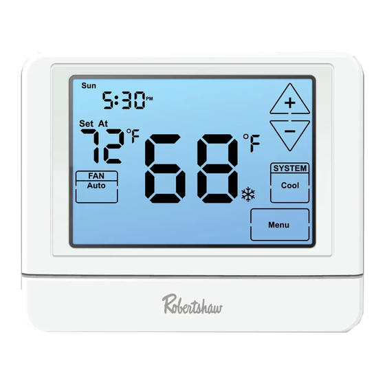
Getting to know your thermostat
WAKE
Sun Mon Tue Wed Thu Fri Sat
Set At
SYSTEM
Heat
Menu
HOLD
FAN
Auto
On
IAQ
Technician
Setup
Next Step
1
Fan Buttons
2
Next Step Buttons
3
Set Time Buttons
4
Program Buttons
5
Menu Buttons
System Buttons
6
7
Set-Point Buttons
5
Battery Cover
5
Button/Battery Access Door
Installation Location
Caution:
Electrical Hazard
Disconnect power before installing this
product. Failure to do so can cause electric
shock or equipment damage.
Mercury Notice
This product is mercury-free. However,
if this product is replacing a control
which contains mercury, it needs to
be disposed of properly. Contact your
local waste management authority for
instructions regarding recycling and
proper disposal of the control.
Thermostat Quick Reference
Sun Mon Tue Wed Thu Fri Sat
Set At
WAKE LEAVE RETURN SLEEP
FAN
Auto
On
IAQ
SYSTEM
Heat ON
Cool
Technician
Auto
Em.heat
Setup
Next Step
Set Time
Set Schedule
Run Schedule
Clean
Hold
Menu
Next Zone
Previous Step
Done
1
Days of the week and time
Indicates the current room
2
temperature
3
Displays the user selectable
set-point temperature
Hold is displayed when thermostat
4
program is overridden.
5
System Operation Indicators:
The compressor delay is active if
these are flashing.
Programmable Time Periods:
6
Residential uses 4 time periods -
WAKE, RETURN, LEAVE and SLEEP.
Program Menu Options:
7
Shows different options during
programming.
Low Battery Indicator: Replace
8
batteries when this indicator is
shown.
2
WAKE LEAVE RETURN SLEEP
SYSTEM
HOLD
Heat Off
Cool
Auto
Em.heat
Set Time
Set Schedule
Run Schedule
Clean
Hold
Menu
Next Zone
Previous Step
Done
4
Advertisement

Related Manuals for Robertshaw RS9320T


Summary of Contents for Robertshaw RS9320T
- Page 1 INSTALLATION MANUAL Installation Location Install the thermostat 4 to 5 feet above the floor in an area with good air RS9320T circulation and average temperature. For new installations, mount thermostat on an inside wall, 4-5 feet above the floor. Do not install the thermostat in the following locations: •...
- Page 2 Wiring Wiring Diagrams Terminal Designations Power supply This thermostat is shipped from the factory to operate a conventional heating Factory-installed jumper. Remove only when installing on and cooling system. This thermostat may also be configured for a heat pump 2-transformer systems. system.
- Page 3 Installer Setup Menu Installer Setup Menu 1. Press MENU. Settings Display Adjustment Options Default 2. Press and hold TECHNICIAN SETUP for 3 seconds. 3. Configure the installer options as desired using the table below. The heating differential is factory to change settings and NEW STEP or PREV STEP to move 4.
- Page 4 Customer Service +1.800.304.6563 HVACCustomerService@robertshaw.com Limited to Scan for Technical Service +1.800.445.8299 Year www.robertshaw.com • 352-00301-001 Warranty Info Warranty HVACCustomerService@robertshaw.com Limited www.robertshaw.com • 352-00301-001 352-00307-001 Rev. B Warranty © 2021 Robertshaw Controls Company. Robertshaw is a trademark of Robertshaw Controls Company. ®...
Need help?
Do you have a question about the RS9320T and is the answer not in the manual?
Questions and answers