
Related Manuals for Critical Environment Technologies CGAS-A


Summary of Contents for Critical Environment Technologies CGAS-A
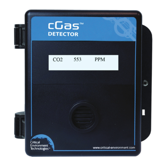
- Page 1 Installation Manual Rev. B | 2021.08 CGAS-A Gas Detector Analog Transmitter www.critical-environment.com...
- Page 2 cGas Detector Analog Transmitter - Installation Manual Rev. B | 2021.08 NEED MORE INFORMATION? This is the Installation Manual for the cGas Detector Analog Transmitter. If you would like it in pdf form, click here to open and download it from our website. If you need more information, refer to the cGAS Detector Operation Manual, which covers topics such as: •...
-
Page 3: Table Of Contents
Rev. B | 2021.08 cGas Detector Analog Transmitter - Installation Manual TABLE OF CONTENTS 1 POLICIES ....................... 5 1.1 Important Note ..................5 1.2 Warranty Policy ..................6 1.3 Service Policy ..................6 1.4 Copyrights ....................7 1.5 Disclaimer ....................7 1.6 Revisions .................... - Page 4 cGas Detector Analog Transmitter - Installation Manual Rev. B | 2021.08 6.4 Protection Against Mechanical Risks ..........24 6.5 Mounting the Transmitter ..............25 6.5.1 Wet Environment Considerations ..........25 6.5.2 EMI and RF Interference Considerations ........26 6.5.3 Mounting Heights (Sensor Dependent) ........26 6.6 Enclosure Mounting Components ............
-
Page 5: Policies
Rev. B | 2021.08 cGas Detector Analog Transmitter - Installation Manual 1 POLICIES 1.1 Important Note Read and understand this manual prior to using this instrument. Carefully read the warranty policy, service policy, notices, disclaimers and revisions on the following pages. This product must be installed by a qualified electrician or factory trained technician and according to instructions indicated in this manual. -
Page 6: Warranty Policy
The product is only to be used for the purposes stated in the manual. Critical Environment Technologies is not liable for auxiliary interfaced equipment or consequential damage. -
Page 7: Copyrights
Rev. B | 2021.08 cGas Detector Analog Transmitter - Installation Manual may contact the distributor from whom it was purchased, or you may contact CETCI directly. Prior to shipping equipment to CETCI, contact our office for an RMA #. All returned goods, regardless of reason, must be accompanied with an RMA number. -
Page 8: Revisions
Should you detect any error or omission in this manual, or should you want to inquire regarding upgrading the device’s firmware, please contact CETCI at the following address: Critical Environment Technologies Canada Inc. Unit 145, 7391 Vantage Way, Delta, BC, V4G 1M3, Canada Toll Free: +1.877.940.8741... -
Page 9: Introduction
2 INTRODUCTION 2.1 General Description Thank you for purchasing our CGAS-A analog cGas Detector, a single sensor, 4 - 20 mA transmitter available with a wide range of sensors and sensor types for continuous monitoring of hazardous gases or oxygen in non-hazardous (non- explosion rated) environments such as commercial HVAC and light industrial applications. - Page 10 , HCI, HCN, O , PH ). The CGAS-A has one analog output which is used for gas readings when configured with a gas sensor; RH and Temperature readings will be locally displayed only. ***Option -RLY is a one SPDT dry contact relay, rated 30 volts, 2 amps max.
-
Page 11: Instrument Specifications
Rev. B | 2021.08 cGas Detector Analog Transmitter - Installation Manual 3 INSTRUMENT SPECIFICATIONS 3.1 Technical Specifications MECHANICAL ABS / Polycarbonate, IP54 rating with splash guard Enclosure installed. Copper coated interior to reduce RF interference. Weight 400 g / 14 oz Size 127 mm x 127 mm x 71 mm / 5.0 in x 5.0 in x 3.0 in Conduit Entry Points... - Page 12 cGas Detector Analog Transmitter - Installation Manual Rev. B | 2021.08 ELECTRICAL 16 - 30 VDC, 3 W, Class 2 12 - 27 VAC, 50-60 Hz, 3 VA, Class 2 Power Requirement 24V recommended. Refer to Section 6.7 Wiring Connections 24 VDC or 24 VAC (ground referenced) 3-conductor Wiring shielded 14-18 AWG stranded within conduit...
- Page 13 Rev. B | 2021.08 cGas Detector Analog Transmitter - Installation Manual CERTIFICATION Model: CGAS-A-XXX S/N: CGASA1807B00010 Rating: 16-30 VDC, 3W, Class 2 12-27 VAC, 50-60 Hz, 3VA, Class 2 CERTIFIED FOR ELECTRIC SHOCK & ELECTRICAL FIRE HAZARD ONLY. LA CERTIFICATION ACNOR COUVRE UNIQUEMENT LES RISQUES DE CHOC ELECTRIQUE ET D’INCENDIE D’ORIGINE ELECTRIQUE.
-
Page 14: Enclosure Dimensions
cGas Detector Analog Transmitter - Installation Manual Rev. B | 2021.08 3.2 Enclosure Dimensions Above dimensions are shown with optional standard splash guard. Without splash guard, thickness is 71 mm / 3.0 in. The area required for enclosure door to be open 90 degrees is 178 mm / 7.0 in or 254 mm / 10.0 in for fully open. With the optional splash guard installed, the enclosure is IP54 rated. -
Page 15: Sensor Specifications
Chlorine Dioxide (ClO CGAS-A-CLO2 0 - 1.0 ppm ~2 yrs Ethylene (C CGAS-A-C2H4 * 0 - 200 ppm ~2 yrs * not suitable for use in applications with continuous exposure to ethylene, i.e. ripening rooms, use LPT-A, LPT-B or LPT-M instead... - Page 16 Detector Analog Transmitter - Installation Manual Rev. B | 2021.08 Hydrogen Cyanide (HCN) CGAS-A-HCN 0 - 30 ppm ~2 yrs Hydrogen Fluoride (HF) CGAS-A-HF 0 - 10.0 ppm ~1-2 yrs Hydrogen Sulphide (H CGAS -A-H2S 0 - 50 ppm...
- Page 17 Rev. B | 2021.08 cGas Detector Analog Transmitter - Installation Manual Refrigerant (R507A) CGAS-A-SR507A 0 - 2,000 ppm ~5 yrs Refrigerant (R513A) CGAS-A-SR513A 0 - 2,000 ppm ~5 yrs Refrigerant (R514A) CGAS A-SR514A 0 - 2,000 ppm ~5 yrs TVOC (Isobutylene)
-
Page 18: Esh-A-Remote Gas Sensor Types
Detector Analog Transmitter - Installation Manual Rev. B | 2021.08 Internal RH & Temp Part Number Sensor (no gas sensor) Relative Humidity and CGAS-A-RHT Temperature No Internal Gas Sensor Part Number Add a remote ESH-A CGAS-A-R sensor 4.2 ESH-A-Remote Gas Sensor Types... -
Page 19: Rh & Temperature Sensor (Option -Rht)
0 - 300 ppm 4.3 RH & Temperature Sensor (Option -RHT) The CGAS-A is a single channel device, it has one analog output. If ordered with an internal or remote gas sensor and a relative humidity and temperature sensor, the analog output signal will be used to send the gas reading signal to a controller or BAS/DDC. -
Page 20: Instrument Features
cGas Detector Analog Transmitter - Installation Manual Rev. B | 2021.08 5 INSTRUMENT FEATURES 5.1 Exterior Enclosure NUMBER FEATURE FUNCTION Secures door to base and allows Door Hinge easy opening and closing LCD display (standard display Display ... -
Page 21: Interior System Layout
Rev. B | 2021.08 cGas Detector Analog Transmitter - Installation Manual 5.2 Interior System Layout NUMBER FEATURE FUNCTION Access menu options and program Programming functions using buttons inside the Buttons enclosure. (Arrow up, Enter, Arrow down) Test Points: TP1 For measuring voltage output ... -
Page 22: Installation
Rev. B | 2021.08 6 INSTALLATION The sensor in the CGAS-A goes through a burn in period at our factory prior to shipping so it is ready for operation upon arrival. If you install the CGAS-A when it arrives, most sensors will not require a long warm up period (about 5 minutes for Ammonia and Nitrogen dioxide, 2 minutes for the other gases, except Oxygen which is a minimum of 2 hours). -
Page 23: General Safety Warnings
Rev. B | 2021.08 cGas Detector Analog Transmitter - Installation Manual After a substantial warm up period, an Ethylene Oxide sensor should be zeroed on site if the ambient temperature is above 22°C (71.6°F). This particular sensor has a drift factor that can be as much as 1 ppm if the temperature rises to 25°C (77°F). -
Page 24: Protection Against Electrical Risks
cGas Detector Analog Transmitter - Installation Manual Rev. B | 2021.08 6.3 Protection Against Electrical Risks Disconnect all power before servicing. There may be multiple power sources. Power supply may have a building installed circuit breaker / switch that is suitably located and easy to access when servicing is required and should be labelled as cGas Detector supply (disconnecting power to the cGas Detector). -
Page 25: Mounting The Transmitter
Rev. B | 2021.08 cGas Detector Analog Transmitter - Installation Manual The enclosure has one screw securing the door to the base for electrical safety and provides an opening to allow the user to apply a padlock or tie wrap if they desire the transmitter to be locked. -
Page 26: Emi And Rf Interference Considerations
cGas Detector Analog Transmitter - Installation Manual Rev. B | 2021.08 Detector enclosure must be liquid tight type. Any water or physical damage to the transmitter that occurs from the installer drilling their own installation holes will not be covered under warranty. 6.5.2 EMI and RF Interference Considerations All electronic devices are susceptible to EMI (Electromagnetic Interference) and RFI (Radio Frequency Interference). - Page 27 Rev. B | 2021.08 cGas Detector Analog Transmitter - Installation Manual Typical Mounting Height by Gas: MOUNTING COVERAGE COVERAGE GAS TYPE HEIGHT (ft2) (m2) on or near the 3000 Ammonia (NH3) ceiling Carbon Dioxide (CO2) breathing zone 3000 Carbon Dioxide (CO2) breathing zone 3000 Carbon Monoxide (CO)
- Page 28 cGas Detector Analog Transmitter - Installation Manual Rev. B | 2021.08 6 in (15 cm) from 3000 Fluorine (F2) floor breathing zone 3000 Formaldehyde (CH2O) 12 in (30 cm) from 3000 Hydrogen Chloride (HCl) floor 12 in (30 cm) from 3000 Hydrogen Cyanide (HCN) floor...
-
Page 29: Enclosure Mounting Components
Rev. B | 2021.08 cGas Detector Analog Transmitter - Installation Manual 12 in (30 cm) from 3000 R123 refrigerant (only) floor target gas 3000 TVOCs dependent 6.6 Enclosure Mounting Components 6.6.1 Enclosure Base ... -
Page 30: Enclosure Bottom
cGas Detector Analog Transmitter - Installation Manual Rev. B | 2021.08 6.6.2 Enclosure Bottom NUMBER FEATURE Door Hinge Conduit Entry Points 12.7 mm / 1/2 in diameter 6.7 Wiring Connections The cGas Detector analog transmitter is a low voltage powered device. Any application of operating voltages higher than indicated in the specification may result in damage. - Page 31 Rev. B | 2021.08 cGas Detector Analog Transmitter - Installation Manual CGAS-A Connected to an FCS Controller (3-wire VDC) If the cGas Detector is being connected to a BAS, DDC or other control panel then either a 24 VDC power supply or 24 VAC Class 2 or better transformer need to be used.
-
Page 32: Analog Wire Gauge Vs Run Length
cGas Detector Analog Transmitter - Installation Manual Rev. B | 2021.08 6.7.1 Analog Wire Gauge vs Run Length The table below shows the maximum cable length between the cGas Detector and the Controller for normal installations (a separate signal line from the controller for each cGas Detector is required). -
Page 33: Wiring The Relay Smart Board (Models With Option -Rly)
6.7.3 ESH-A Remote Sensor Wiring Connection Each ESH-A is given the same serial number as the device it is being connected to. Make sure to connect the ESH-A to the CGAS-A that has the same serial number or the factory calibration will be void. - Page 34 cGas Detector Analog Transmitter - Installation Manual Rev. B | 2021.08 Wiring Example: ESH-A Remote Sensor Note: The maximum length of wire between the ESH-A Remote Sensor and the cGas Detector should not exceed 15 m (50 ft). © 2021 All rights reserved. Data subject to change without notice.
-
Page 35: Basic System Operation
Rev. B | 2021.08 cGas Detector Analog Transmitter - Installation Manual 7 BASIC SYSTEM OPERATION The cGas Detector continuously monitors gas concentrations on one configured channel. It must be connected to a controller (FCS, DCC or SCC), a control panel or a BAS / BMS / DDC system; the cGas Detector is not a standalone gas detection system. -
Page 36: Navigating The Menu Structure
cGas Detector Analog Transmitter - Installation Manual Rev. B | 2021.08 All sensors are calibrated in the factory prior to shipping and should not require calibration at the time of a routine installation or replacement. 7.2 Navigating the Menu Structure The three programming push-buttons inside the enclosure are used to navigate through the cGas Detector menu structure. -
Page 37: Display Settings
Rev. B | 2021.08 cGas Detector Analog Transmitter - Installation Manual CODE NAME DESCRIPTION • Test Analog Output 0001 Test Menu • Test Relay (if Option -RLY is installed) • Display Type 1014 Display Menu • Brightness • Hide Channel 7.4 Display Settings The LCD display can display up to 2-lines of 16-characters. -
Page 38: Display Configurations
cGas Detector Analog Transmitter - Installation Manual Rev. B | 2021.08 digit by pressing ENTER. When finished, press ENTER to confirm and Exit. Brightness Confirm? >050 >Y NOTE: You cannot enter a number higher than 100. Entering a value of 000 turns the backlight off completely. -
Page 39: Alarm Status, Fault Detection And Communication Failure Alerts
Rev. B | 2021.08 cGas Detector Analog Transmitter - Installation Manual 7.5 Alarm Status, Fault Detection and Communication Failure Alerts If a channel is in alarm, the following letters will be displayed at the end of the line for that channel. •... -
Page 40: Temperature And/Or Relative Humidity Offset
cGas Detector Analog Transmitter - Installation Manual Rev. B | 2021.08 In the Selected Channel menu, if Temperature is not displayed, press ENTER and use the UP button to scroll to find Temperature. Press ENTER. Selected Channel Selected Channel >Temperature Use the UP button to find Temperature Unit. -
Page 41: Test Functions
Rev. B | 2021.08 cGas Detector Analog Transmitter - Installation Manual Calibrate Menu Press Enter In the Selected Channel menu, if Temperature (or Humidity) is not displayed, press ENTER and use the UP button to scroll to find the item you are looking for. Press ENTER. -
Page 42: Test Relay (Models With Option -Rly)
cGas Detector Analog Transmitter - Installation Manual Rev. B | 2021.08 Enter Password 0001 Press ENTER to access the Test Menu. Test Menu Press Enter In the Test AO menu, the default entry is 4 mA. Press ENTER. Test AO 4.0 mA Enter the preferred output value between 0 and 30 mA by using the UP, DOWN and ENTER buttons, or to continue with 4 mA press ENTER to the end. -
Page 43: Troubleshooting
Rev. B | 2021.08 cGas Detector Analog Transmitter - Installation Manual In the Test Relay menu, the default entry is Untripped. Press ENTER and use the UP button to change to Tripped. Press ENTER. You will hear a soft click and the relay will activate accordingly, respecting its failsafe setting. - Page 44 cGas Detector Analog Transmitter - Installation Manual Rev. B | 2021.08 List of Possible cGas Error Codes: (appears on the display in place of the units for a channel) CODE DESCRIPTION Check to make sure the smart sensor board is present and installed properly in the socket. If installed, the cGas detects the sensor signal Negative Fault is too far below its zeroAD.
- Page 45 Rev. B | 2021.08 cGas Detector Analog Transmitter - Installation Manual Firmware expected a different smart board than what is in the sensor socket. Confirm the correct smart board is installed in the SB ID Mismatch correct socket. ie. CH1 gas should be in the left socket.
- Page 46 cGas Detector Analog Transmitter - Installation Manual Rev. B | 2021.08 NOTES © 2021 All rights reserved. Data subject to change without notice.
- Page 47 Rev. B | 2021.08 cGas Detector Analog Transmitter - Installation Manual NOTES © 2021 All rights reserved. Data subject to change without notice.
- Page 48 SAFER AIR EVERYWHERE. www.critical-enviroment.com CGAS-A-20210817-Rev-B Unit 145, 7391 Vantage Way, Delta, BC V4G 1M3 Canada Tel: +1.604.940.8741 Toll Free: +1.877.940.8741 © 2021 All rights reserved. Data subject to change without notice.
Need help?
Do you have a question about the CGAS-A and is the answer not in the manual?
Questions and answers