
Related Manuals for Critical Environment Technologies LPT Series


Summary of Contents for Critical Environment Technologies LPT Series
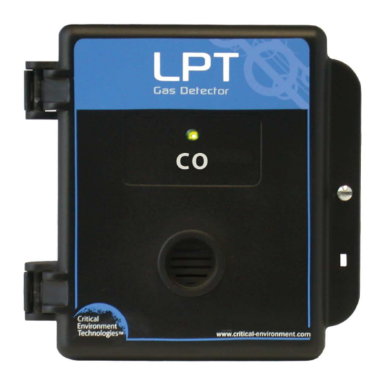
- Page 1 Operation Manual Rev. E | 2021.03 Low Power Transmitter www.critical-environment.com...
-
Page 2: Table Of Contents
LPT - Operation Manual Rev. E | 2021.03 TABLE OF CONTENTS 1 POLICIES ......................5 1.1 Important Note ....................5 1.2 Warranty Policy ....................6 1.3 Service Policy ....................6 1.4 Copyrights ......................8 1.5 Disclaimer ......................8 1.6 Revisions ......................8 2 INTRODUCTION ..................... 9 2.1 General Description ..................9 2.2 Key Features ....................10 3 INSTRUMENT SPECIFICATIONS ..............11... - Page 3 Rev. E | 2021.03 LPT - Operation Manual 6.5 Mounting the Transmitter ................19 6.5.1 Wet Environment Considerations ..............6.5.2 EMI and RF Interference Considerations ............6.5.3 Sensor Mounting Height (Sensor Dependent) ..........6.6 Enclosure Mounting Components ..............22 6.6.1 Enclosure Base ....................6.6.2 Enclosure Bottom ....................
- Page 4 LPT - Operation Manual Rev. E | 2021.03 9 ACCESSORIES ....................39 9.1 Splash Guard ....................39 9.2 Calibration Adapter Clip “Cal Clip” ..............40 9.3 Metal Protective Guard ..................40 9.4 Calibration Kit ....................41 10 MAINTENANCE ..................42 11 TROUBLE SHOOTING ................42 © 2021 All rights reserved. Data subject to change without notice.
-
Page 5: Policies
Rev. E | 2021.03 LPT - Operation Manual 1 POLICIES 1.1 Important Note Read and understand this manual prior to using this instrument. Carefully read the warranty policy, service policy, notices, disclaimers and revisions on the following pages. This product must be installed by a quali ed electrician or trained technician and according to instructions indicated in this manual. -
Page 6: Warranty Policy
The product is only to be used for the purposes stated in the manual. Critical Environment Technologies is not liable for auxiliary interfaced equipment or consequential damage. -
Page 7: Copyrights
RMA number. If CETCI is to do the repair work, you may send the instrument, prepaid, to: Attention: Service Department Critical Environment Technologies Canada Inc. Unit 145, 7391 Vantage Way Delta, BC, V4G 1M3 You must include your Returned Merchandise Authorization (RMA) number, address, telephone number, contact name, shipping / billing information, and a description of the defect as you perceive it. -
Page 8: Revisions
CETCI or visiting www.critical-environment.com. Should you detect any error or omission in this manual, please contact CETCI at the following address: Critical Environment Technologies Canada Inc. Unit 145, 7391 Vantage Way, Delta, BC, V4G 1M3, Canada Toll Free: +1.877.940.8741... -
Page 9: Introduction
Rev. E | 2021.03 LPT - Operation Manual In no event will CETCI, its o cers or employees be liable for any direct, special, incidental or consequential damages resulting from any defect in any manual, even if advised of the possibility of such damages. -
Page 10: Key Features
LPT - Operation Manual Rev. E | 2021.03 2.2 Key Features • Single sensor • 2-wire loop, 3-wire VDC or 4-wire VAC power • Linear 4 - 20 mA output signal • Standard water / dust tight, corrosion resistant enclosure (drip proof) •... - Page 11 Rev. E | 2021.03 LPT - Operation Manual ELECTRICAL Power Requirement 2-wire mode 16 - 30 VDC, 1 W, Class 2 3-wire mode 16 - 30 VDC, 1 W, Class 2 4-wire mode 12 - 27 VAC, 50 - 60 Hz, 1 VA, Class 2 Use Class 2 transformer.
- Page 12 LPT - Operation Manual Rev. E | 2021.03 Operating Humidity 15 - 90% RH non-condensing CERTIFICATION Model: LPT-XXX S/N: LPT1601E00374 Rating: 16-30 VDC, 1W, Class 2 12-27 VAC, 50-60 Hz 1VA, Class 2 CERTIFIED FOR ELECTRIC SHOCK & ELECTRICAL FIRE HAZARD ONLY. LA CERTIFICATION ACNOR COUVRE UNIQUEMENT LES RISQUES DE CHOC ELECTRIQUE ET D’INCENDIE D’ORIGINE ELECTRIQUE.
-
Page 13: Enclosure Dimensions
Rev. E | 2021.03 LPT - Operation Manual 3.2 Enclosure Dimensions 5.0” (127 mm) 1.91” (48.5 mm) 2.24” (57 mm) with splash guard (not shown) © 2021 All rights reserved. Data subject to change without notice. -
Page 14: Sensor Specifications
LPT - Operation Manual Rev. E | 2021.03 4 SENSOR SPECIFICATIONS 4.1 List of Available Internal Sensors Internal Electrochemical Part Number Range Lifespan Sensors Ammonia (NH LPT-NH3 0 - 500 ppm ~2 years Carbon Monoxide (CO) LPT-TCO 0 - 200 ppm ~3 years Chlorine (Cl LPT-CL2... -
Page 15: Features & Functions
Rev. E | 2021.03 LPT - Operation Manual 5 FEATURES & FUNCTIONS 5.1 Exterior Enclosure Œ • Ž • • Œ NUMBER FEATURE FUNCTION Door Hinge Secures door Œ LED Indicator Indicates Power & Fail • Door Screw Secures door Ž... -
Page 16: Interior System Layout
LPT - Operation Manual Rev. E | 2021.03 5.2 Interior System Layout Œ Ž • • NUMBER FEATURE FUNCTION Jumpers For calibrations & test functions Œ Test Points: TP-1 & TP-2 For measuring voltage output • Wiring Terminal Pluggable wiring terminal Ž... -
Page 17: Installation
Rev. E | 2021.03 LPT - Operation Manual 6 INSTALLATION The sensor in the LPT goes through a burn in period at our factory prior to shipiping so it is ready for operation upon arrival. If you install the LPT when it arrives, most sensors will not require a long warm up period (about 5 minutes for Ammonia and Nitrogen dioxide, 2 minutes for the other gases, except Oxygen which is a minimum of 2 hours). -
Page 18: General Safety Warnings
LPT - Operation Manual Rev. E | 2021.03 A bump test will help you determine if a sensor requires calibration. If the sensor still does not respond as it should after a successful calibration, it probably requires replacing. 6.2 General Safety Warnings The LPT is intended for indoor use, permanently mounted at a height that is appropriate for the type of gas being monitored. -
Page 19: Protection Against Mechanical Risks
Rev. E | 2021.03 LPT - Operation Manual 6.4 Protection Against Mechanical Risks The door of the ABS / polycarbonate enclosure can be removed if absolutely necessary to facilitate installation of the base but it is not recommended on this version. Extreme care and caution must be exercised when removing the door to avoid damaging the hinges. -
Page 20: Wet Environment Considerations
LPT - Operation Manual Rev. E | 2021.03 enclosure base. One in the rear of the base and one on the bottom edge of the base. See Section 5.7 Enclosure Mounting Components. The clearance from the PCA to the base enclosure is 12.7 mm (½ in). Do not use a conduit connector that has more than 12.7 mm (½... -
Page 21: Sensor Mounting Height (Sensor Dependent)
Rev. E | 2021.03 LPT - Operation Manual There are some installation procedures that will reduce the likelihood of getting faulty readings: 1. Locate the detectors and controllers out of the way from normal foot tra c and high energy equipment. 2. -
Page 22: Enclosure Mounting Components
LPT - Operation Manual Rev. E | 2021.03 NOTE: CETCI considers 4 - 6 ft from the oor as the “Breathing Zone” when it applies to sensors installed for vehicle exhaust applications. 6.6 Enclosure Mounting Components 6.6.1 Enclosure Base Ž Ž... -
Page 23: Enclosure Bottom
Rev. E | 2021.03 LPT - Operation Manual 6.6.2 Enclosure Bottom Œ • NUMBER FEATURE Door Hinge Œ Conduit Entry • 6.7 Wiring Connections The LPT analog transmitter is a low voltage powered device. Any application of operating voltages higher than indicated in the speci cation may result in damage. Double check wiring connections prior to powering the transmitter. -
Page 24: Power & Output Connection
LPT - Operation Manual Rev. E | 2021.03 6.7.1 Power Connection If the installer is powering the LPT with 24 VAC, both VAC wires should be connected to the terminal “one” and terminal “two”, from the top down. If the installer is powering the LPT with 24 VDC three wire, the “positive” wire should be connected to terminal “one”... -
Page 25: Wire Gauge Vs Run Length
Rev. E | 2021.03 LPT - Operation Manual 6.7.2 Wire Gauge vs Run Length MAXIMUM LOAD MAXIMUM CABLE SUPPLY VOLTAGE (Wire + Termination WIRE GAUGE (awg) LENGTH (feet) Resistor) (ohms) 4,400 24 VDC 7,100 10,700 216 (assume a 200 Ω 16 VDC 1,200 termination resistor) -
Page 26: Open Loop
LPT - Operation Manual Rev. E | 2021.03 during the warm up period. This is normal and the length of time the gas alarms exist is dependent upon the length of time since the unit was last powered up and the state of the environment it is installed in. -
Page 27: Test Functions
Rev. E | 2021.03 LPT - Operation Manual 7.3 Test Functions During warm up and normal operation, the current loop and the voltage output can be tested by using Jumpers on J2 (refer to Section 7.4 Jumpers). Place the rst Jumper to set the gas output level (GAS3, GAS2, GAS1), then place the second Jumper to the OVER pins. - Page 28 LPT - Operation Manual Rev. E | 2021.03 FUNCTION DESIRED (example) J2 JUMPER-1 J2 JUMPER-2 Setting Span Gas Value GAS3 IDLE (CO = 200 ppm, NO = 10 ppm) Setting Span Gas Value GAS2 IDLE (CO = 100 ppm, NO = 5 ppm) Setting Span Gas Value GAS1...
- Page 29 Rev. E | 2021.03 LPT - Operation Manual The three upper jumper’s (GAS1-GAS3) allow setting the calibration gas value. The OVER jumper setting allows overriding the value if out of range during calibration but still at a “reasonable” value. The default factory set location are as shown, (Jumper-1) is in the GAS3 position and the lower jumper (Jumper-2) is in the IDLE position.
-
Page 30: Calibration
LPT - Operation Manual Rev. E | 2021.03 8 CALIBRATION 8.1 Calibration Speci cations 8.1.1 Gas Calibration span gases should have at least ± 5% accuracy and have a current date stamp. Gas generators should have a current dated cell installed. Service personnel should ow zero emissions air or 20.9% volume O (scrubbed of hydrocarbons) before attempting to null adjust toxic gas sensors. -
Page 31: Calibration Frequency
Rev. E | 2021.03 LPT - Operation Manual 8.1.4 Calibration Frequency • Parking garage detectors: Once every 12 months • OHS applications: Once every 6 months (OHS: Occupational Health & Safety) • For best performance and to meet published speci cations: once every six months NOTE: A calibration label should be applied after every calibration to con rm work performed and the date it was con rmed. -
Page 32: Calibrating The Internal Sensor
LPT - Operation Manual Rev. E | 2021.03 It is also suggested that when calibrating a Chlorine sensor, you use a chlorine gas generator due to the instability of Chlorine gas in a cylinder and the fact that it is di cult to get accurate readings from that source. - Page 33 Rev. E | 2021.03 LPT - Operation Manual GAS3 500 ppm 4.00 VDC 0 - 500 ppm GAS2 300 ppm 2.40 VDC GAS1 50 ppm 0.40 VDC GAS3 10 ppm 4.00 VDC 0 - 10 ppm GAS2 5 ppm 2.00 VDC GAS1 3 ppm 1.20 VDC...
- Page 34 LPT - Operation Manual Rev. E | 2021.03 Step 2: Attach regulator to cylinder of zero air, insert calibration adapter into the sensor opening in the front of the enclosure door, and open regulator valve fully allowing zero air to ow over sensor for one minute.
- Page 35 Rev. E | 2021.03 LPT - Operation Manual Step 6: Attach regulator to cylinder of span gas. Step 7: Insert the calibration adapter into the sensor opening in the front of the enclosure door. Step 8: Open regulator valve fully and allow span gas to ow over sensor. If no gas is detected after one minute, the transmitter returns to normal operation and the procedure will need to be performed from Step 2.
-
Page 36: Calibrating An Oxygen Sensor
LPT - Operation Manual Rev. E | 2021.03 If the sensitivity of the sensor is calculated out of range more than the OVER can compensate for, the internal LED will turn on solid, the front LED will remain o and the current loop will output 20 mA indicating the sensor cannot be calibrated. - Page 37 Rev. E | 2021.03 LPT - Operation Manual To achieve calibration, the user must go through the following steps: Step 1: Indicate what concentration of span gas used to ow over the sensor by putting Jumper-1 into gas position (GAS1, GAS2 or GAS3). SENSOR JUMPER-1 SPAN GAS...
- Page 38 LPT - Operation Manual Rev. E | 2021.03 a slight twisting motion as you gently push the calibration adapter into the sensor opening. If the calibration adapter is hard to insert, moisten the O-ring seal slightly then try re-inserting it. If the optional splash guard is installed, slide the Cal Clip around the splash guard and attach the tubing to the nozzle on the Cal Clip.
-
Page 39: Accessories
Rev. E | 2021.03 LPT - Operation Manual move to IDLE position before the zeroing is nished and the transmitter will return to normal operation (solid green light on the front). If the zero is out of range but within the override range, the LED will ash. To override, move the concentration jumper to the OVER position. -
Page 40: Calibration Adapter Clip "Cal Clip
LPT - Operation Manual Rev. E | 2021.03 9.2 Calibration Adapter Clip “Cal Clip” p/n: CET-SGC To calibrate an LPT with a factory installed splash guard (Option -S), attach the Cal Clip around the splash guard. The small barb hose tting accommodates standard or Te on tubing of 1/8” (3.175 mm) ID and 3/16”... -
Page 41: Calibration Kit
Rev. E | 2021.03 LPT - Operation Manual Enclosure 16 gauge galvanized steel Weight 800 g (28 oz) Size 178 mm W x 160 mm H x 91 mm D / 7.0 in W x 6.3 in H x 3.6 in D 9.4 Calibration Kit p/n: CET-715A-CK1 The Calibration Kit contains the items necessary for common eld... -
Page 42: Maintenance
LPT - Operation Manual Rev. E | 2021.03 10 MAINTENANCE The LPT transmitter requires virtually no maintenance other than regular calibration of the sensor. The transmitter should be monitored for possible damaging conditions. 4. The sensor port should be kept free of dirt or soot build up. 5. - Page 43 Rev. E | 2021.03 LPT - Operation Manual During calibration the internal LED will blink long ON and short OFF. The sensor needs override. Move Jumper-1 to OVER position. The internal LED turn solid green and the outside LED remains OFF. It failed calibration.
- Page 44 Critical Environment Technologies Canada Inc. Unit 145, 7391 Vantage Way, Delta, BC, V4G 1M3, Canada Toll Free: +1.877.940.8741 Tel: +1.604.940.8741 www.critical-environment.com LPT20210308-E © 2021 Critical Environment Technologies Canada Inc. All rights reserved. Data in this publication may change without notice.
Need help?
Do you have a question about the LPT Series and is the answer not in the manual?
Questions and answers