
Subscribe to Our Youtube Channel
Related Manuals for Critical Environment Technologies CGAS-A


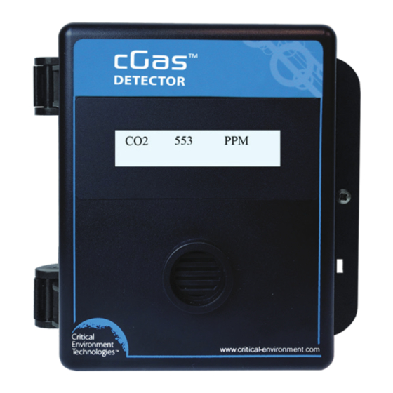
Summary of Contents for Critical Environment Technologies CGAS-A
- Page 1 Installation Manual Rev. C | 2023.03 CGAS-A Detector Analog Transmitter www.critical-environment.com...
- Page 2 cGas Detector Analog Transmitter - Installation Manual Rev. C | 2023.03 NEED MORE INFORMATION? This is the Installation Manual for the cGas Detector Analog Transmitter. If you would like to make sure you have the most current version or want to save it in pdf form, click here to view or download from our website.
-
Page 3: Table Of Contents
Rev. C | 2023.03 cGas Detector Analog Transmitter - Installation Manual TABLE OF CONTENTS 1 POLICIES ....................... 5 1.1 Important Note ..................5 1.2 Warranty Policy ..................6 1.3 Service Policy ..................6 1.4 Copyrights ....................7 1.5 Disclaimer ....................7 1.6 Revisions .................... - Page 4 cGas Detector Analog Transmitter - Installation Manual Rev. C | 2023.03 6.4 Protection Against Mechanical Risks ..........25 6.5 Mounting the Transmitter ..............26 6.5.1 Wet Environment Considerations ..........27 6.5.2 EMI and RF Interference Considerations ........27 6.5.3 Mounting Heights (sensor and application dependent) ..28 6.6 Enclosure Mounting Components ............
-
Page 5: Policies
Rev. C | 2023.03 cGas Detector Analog Transmitter - Installation Manual 1 POLICIES 1.1 Important Note Read and understand this manual prior to using this instrument. Carefully read the warranty policy, service policy, notices, disclaimers and revisions on the following pages. This product must be installed by a qualified electrician or factory trained technician and according to instructions indicated in this manual. -
Page 6: Warranty Policy
The product is only to be used for the purposes stated in the manual. Critical Environment Technologies is not liable for auxiliary interfaced equipment or consequential damage. -
Page 7: Copyrights
Rev. C | 2023.03 cGas Detector Analog Transmitter - Installation Manual may contact the distributor from whom it was purchased, or you may contact CETCI directly. Prior to shipping equipment to CETCI, contact our office for an RMA #. All returned goods, regardless of reason, must be accompanied with an RMA number. -
Page 8: Revisions
Should you detect any error or omission in this manual, or should you want to inquire regarding upgrading the device’s firmware, please contact CETCI at the following address: Critical Environment Technologies Canada Inc. Unit 145 - 7391 Vantage Way, Delta, BC V4G 1M3 Canada Toll Free: +1.877.940.8741... -
Page 9: Introduction
HVAC, greenhouses, recreational facilities, refrigeration plants, manufacturing plants and other light industrial applications. The CGAS-A transmitter is available with internal or remote sensor and operates by diffusion. The sensors utilized in this device are accurate enough to measure to Occupational Health &... - Page 10 • A low temperature package with OLED display and internal heater for cold environment applications down to -40°C / -40°F • Available with all models except CGAS-A-EETO **Option -RBZ • 1 SPDT dry contact relay, rated 30 volts, 2 amp max with internal buzzer rated 90 dB @ 10 cm / 4 in •...
-
Page 11: Instrument Specifications
Rev. C | 2023.03 cGas Detector Analog Transmitter - Installation Manual buzzer. If after reading through the manual, you have any questions, please do not hesitate to contact our service department for technical support. 3 INSTRUMENT SPECIFICATIONS 3.1 Technical Specifications MECHANICAL ABS / Polycarbonate, IP54 rating with splash guard Enclosure... - Page 12 cGas Detector Analog Transmitter - Installation Manual Rev. C | 2023.03 Internal port for USB memory stick connection for in USB Port field configuration updates and firmware upgrades Initiate calibration and menu options with internal UP, Push Buttons DOWN and ENTER push buttons Rated 90dB @ 10 cm / 4in, user enable/disable Comes standard with all 7 series electrochemical Audible Alarm...
- Page 13 Pollution Degree Degree 2 Altitude below 2,000 m CERTIFICATION Model: CGAS-A-XXX S/N: CGASA1807B00010 Rating: 16-30 VDC, 3W, Class 2 12-27 VAC, 50-60 Hz, 3VA, Class 2 CERTIFIED FOR ELECTRIC SHOCK & ELECTRICAL FIRE HAZARD ONLY. LA CERTIFICATION ACNOR COUVRE UNIQUEMENT LES RISQUES DE CHOC ELECTRIQUE ET D’INCENDIE D’ORIGINE ELECTRIQUE.
-
Page 14: Enclosure Dimensions
cGas Detector Analog Transmitter - Installation Manual Rev. C | 2023.03 3.2 Enclosure Dimensions Above dimensions are shown with optional standard splash guard. Without splash guard, thickness is 71 mm / 3.0 in. The area required for enclosure door to be open 90 degrees is 178 mm / 7.0 in or 254 mm / 10.0 in for fully open. With the optional splash guard installed, the enclosure is IP54 rated. -
Page 15: Sensor Specifications
4 SENSOR SPECIFICATIONS 4.1 Internal Gas Sensor Types Internal 4 Series Part Number Range Lifespan Electrochemical Sensors Carbon Monoxide (CO) CGAS-A-CO 0 - 200 ppm ~3+ yrs Ethylene Oxide (C CGAS-A-EETO 0 - 20 ppm ~2 yrs Formaldehyde (CH CGAS-A-CH2O... - Page 16 Detector Analog Transmitter - Installation Manual Rev. C | 2023.03 Chlorine Dioxide (ClO CGAS-A-7CLO2 0 - 1 ppm ~2 yrs Ethylene (C CGAS-A-7C2H4 * 0 - 200 ppm ~2 yrs Fluorine (F CGAS-A-7F2 0 - 1 ppm ~2 yrs...
- Page 17 Rev. C | 2023.03 cGas Detector Analog Transmitter - Installation Manual Refrigerants: R134A, R143A, R22, R32, R227ea, R402A, R404A, R407A, R407C, R407F, R410A, R417A, R422A, CGAS-A-IR134A R422D, R427A, R434A, CGAS-A-IR143A R438A, R442A, R448A, CGAS-A-IR22 0 - 2,000 ppm ~8 yrs...
- Page 18 Detector Analog Transmitter - Installation Manual Rev. C | 2023.03 Internal Catalytic Part Number Range Lifespan (Combustible) Sensors CGAS-A- Butane (C 0 - 100% LEL ~5 yrs CC4H10-100 Ethanol or Dimethyl CGAS-A- 0 - 100% LEL ~5 yrs Ether (C...
-
Page 19: Esh-A-Remote Gas Sensor Types
Rev. C | 2023.03 cGas Detector Analog Transmitter - Installation Manual No Internal Gas Sensor Part Number Add a remote ESH-A CGAS-A-R sensor 4.2 ESH-A-Remote Gas Sensor Types Remote Catalytic Part Number Range Lifespan (Combustible) Sensors ESH-A- CC2H2- 0 - 100% LEL... -
Page 20: Rh & Temperature Sensor (Option -Rht)
Rev. C | 2023.03 4.3 RH & Temperature Sensor (Option -RHT) The CGAS-A is a single channel device, it has one analog output. If ordered with an internal or remote gas sensor and a relative humidity and temperature sensor, the analog output signal will be used to send the gas reading signal to a controller or BAS/DDC. -
Page 21: Instrument Features
Rev. C | 2023.03 cGas Detector Analog Transmitter - Installation Manual 5 INSTRUMENT FEATURES 5.1 Exterior Enclosure NUMBER FEATURE FUNCTION Secures door to base and allows Door Hinge easy opening and closing LCD display (standard display Display ... -
Page 22: Interior System Layout
cGas Detector Analog Transmitter - Installation Manual Rev. C | 2023.03 5.2 Interior System Layout NUMBER FEATURE FUNCTION Access menu options and program Programming functions using buttons inside the Buttons enclosure. (Arrow up, Enter, Arrow down) Test Points: TP1 For measuring voltage output ... -
Page 23: Installation
6 INSTALLATION The sensor in the CGAS-A goes through a burn in period at our factory prior to shipping so it is ready for operation upon arrival. When installing the cGas Detector for the first time, the sensor may require a long warm up time (24 to 48 hours) to stabilize and provide accurate readings. -
Page 24: General Safety And Maintenance Warnings
cGas Detector Analog Transmitter - Installation Manual Rev. C | 2023.03 Ammonia sensors should be left to warm up for 48 hours so the sensor can stabilize. Ozone sensors are sensitive and may be reactive to temperature changes causing them to drift. Silicone, lead and chlorinated hydrocarbon vapours can poison catalytic sensors. -
Page 25: Protection Against Electrical Risks
Rev. C | 2023.03 cGas Detector Analog Transmitter - Installation Manual If painting is to be done in the same area, the gas detector needs to be protected from over spray and the sensor vent should be covered so as to not receive paint fumes. -
Page 26: Mounting The Transmitter
cGas Detector Analog Transmitter - Installation Manual Rev. C | 2023.03 base should “snap” apart from the part of the hinges located on the door. After installation, place the door hinges over the installed base hinges, with the unit fully open and push towards the wall. The hinges should easily “snap” back into place. -
Page 27: Wet Environment Considerations
Rev. C | 2023.03 cGas Detector Analog Transmitter - Installation Manual 6.5.1 Wet Environment Considerations If the cGas Detector is to be installed in a potential hose-down application or any application whereby liquid could be directed towards the sensor opening, the cGas Detector should be ordered with an optional attached splash guard (factory installed). -
Page 28: Mounting Heights (Sensor And Application Dependent)
cGas Detector Analog Transmitter - Installation Manual Rev. C | 2023.03 6.5.3 Mounting Heights (sensor and application dependent) The gas detector needs to be mounted where it will best detect the target gas. Some applications may require some adjustments, but generally speaking, the mounting height will depend on the density of the target gas relative to air. - Page 29 Rev. C | 2023.03 cGas Detector Analog Transmitter - Installation Manual Propane (C3H8) 6 in (15 cm) from 3000 (combustible) floor Methane (CH4) on or near the 5000 (combustible) ceiling Hydrogen (H2) on or near the 5000 (combustible) ceiling Ethanol (C2H6O) 6 in (15 cm) from 3000 (alcohol)
-
Page 30: Enclosure Mounting Components
cGas Detector Analog Transmitter - Installation Manual Rev. C | 2023.03 Oxygen (O2) breathing zone 5000 6 in (15 cm) from Ozone (O3) 3000 floor Phosphine (PH3) breathing zone 3000 Silane (SiH4) breathing zone 3000 6 in (15 cm) from Sulphur Dioxide (SO2) 3000 floor... -
Page 31: Enclosure Bottom
Rev. C | 2023.03 cGas Detector Analog Transmitter - Installation Manual NUMBER FEATURE Door Hinge Conduit Entry Points 12.7 mm / 1/2 in diameter Mounting Holes 4.47 mm / 0.175 in diameter maximum head diameter 8 mm / 0.32 in, #8 or 4 mm screw 6.6.2 Enclosure Bottom ... - Page 32 CGAS-A Connected to an FCS Controller (3-wire VDC) If the cGas Detector is being connected to a BAS, DDC or other control panel then either a 24 VDC power supply or 24 VAC Class 2 or better transformer need to be used.
-
Page 33: Analog Wire Gauge Vs Run Length
Rev. C | 2023.03 cGas Detector Analog Transmitter - Installation Manual TERMINAL STRIP. When using solid core wiring for distribution (in the conduit), use stranded wire pigtails 14 - 18 AWG within the enclosure to connect to the circuit board. The rigidity of solid-core wire can pull a soldered terminal strip completely off a circuit board and this will not be covered under warranty. -
Page 34: Wiring The Relay (If Installed)
• Solid state refrigerant gas sensors • PID TVOC gas sensors If only a relay is needed, Option RLY can be added to a CGAS-A model with a: • 4 series electrochemical toxic gas sensor © 2023 All rights reserved. Data subject to change without notice. -
Page 35: Esh-A Remote Sensor Wiring Connection
6.7.3 ESH-A Remote Sensor Wiring Connection Each ESH-A is given the same serial number as the device it is being connected to. Make sure to connect the ESH-A to the CGAS-A that has the same serial number or the factory calibration will be void. - Page 36 cGas Detector Analog Transmitter - Installation Manual Rev. C | 2023.03 from the signal output, and should not exceed 15 m (50 ft). The voltage at the remote sensor (Red V+ to Black GND) should not be below 4.5 volts. If this voltage is not met after installation, the wrong gauge wire may have been used or the wiring run is too long.
-
Page 37: Power Draw Requirements
It can be connected to a controller (FCS, DCC or SCC), a control panel or a BAS / BMS / DDC system. If the relay and buzzer is installed, the CGAS-A can operate as standalone device. NOTE: For functions that do not appear in this section, refer to the cGAS... -
Page 38: Power-Up And Warm-Up Process From The Factory
cGas Detector Analog Transmitter - Installation Manual Rev. C | 2023.03 Detector Operation Manual. 7.1 Power Up and Warm-up Process from the Factory Upon application of power to a cGas Detector shipped from the factory, the LCD display will turn on and rotate through several info screens that differ depending on the configuration of the transmitter. -
Page 39: Accessing The Menu With Passcodes
Rev. C | 2023.03 cGas Detector Analog Transmitter - Installation Manual ENTER begins a process or moves you to the next screen in the same menu. The UP or DOWN buttons are used to enter characters/numbers and to navigate to the next menu item. For simplicity’s sake, directions in this manual use the UP button. -
Page 40: Display Settings
cGas Detector Analog Transmitter - Installation Manual Rev. C | 2023.03 • Set Analog Output Type • Set Analog Output Zero • Set Analog Output Range 3032 Calibrate Menu • Temperature Offset* • Humidity Offset * • Temperature Units * * Option RHT must be installed 7.4 Display Settings The LCD display can display up to 2-lines of 16-characters. -
Page 41: Display Configurations
Rev. C | 2023.03 cGas Detector Analog Transmitter - Installation Manual Brightness Confirm? >050 >Y NOTE: You cannot enter a number higher than 100. Entering a value of 000 turns the backlight off completely. With ambient light the text can still be read on the display. -
Page 42: Change Analog Output From Milliamps To Voltage
cGas Detector Analog Transmitter - Installation Manual Rev. C | 2023.03 • mid for mid alarm • high for High alarm 1000 mid 1200 high The cGas Detector has built in fault detection, and in the event of a problem with the measurement circuitry the transmitter will indicate a fault condition on the display. - Page 43 Rev. C | 2023.03 cGas Detector Analog Transmitter - Installation Manual Press ENTER to access the Calibrate Menu. Calibrate Menu Press Enter Use the UP button to find Set AO Type. Press ENTER. Set AO Type Set AO Type Current (mA) >Voltage (V) Use the UP button to find Voltage (V).
-
Page 44: Change Units ( C Or F) Of Temperature Readings
cGas Detector Analog Transmitter - Installation Manual Rev. C | 2023.03 Confirm? >08.0 V >Y The Set AO Zero value is the current or voltage at which the device signals no (zero) gas. The Set AO Range value is the current or voltage at which the device signals maximum gas. -
Page 45: Temperature And/Or Relative Humidity Offset
Rev. C | 2023.03 cGas Detector Analog Transmitter - Installation Manual 7.8 Temperature and/or Relative Humidity Offset NOTE: This menu item only applies if the cGas Detector has the -RHT option installed. NOTE: Depending on the configuration, the device will show the temperature in either Celsius or Fahrenheit. -
Page 46: Test Functions
cGas Detector Analog Transmitter - Installation Manual Rev. C | 2023.03 Temperature Adj Humidity Adj >-4.0 degC >+02 %RH Press ENTER to confirm the value is correct. If you entered the wrong value, press the UP button to move the cursor to N and press ENTER and reenter the value. -
Page 47: Test Relay And Buzzer (If Installed)
Rev. C | 2023.03 cGas Detector Analog Transmitter - Installation Manual press ENTER to the end. Test AO >14.0 mA When finished, press ENTER and then again to Confirm Y. Confirm? Test AO >14.0 mA >Y 14.0 mA The test will start as soon as you press ENTER to confirm. To stop the test, press the UP or DOWN button. -
Page 48: Troubleshooting
cGas Detector Analog Transmitter - Installation Manual Rev. C | 2023.03 Test RLY: Test RLY: Untripped >Tripped To stop the relay test, change the entry to Untripped. You will hear a soft click and the relay will deactivate. Test RLY: >Untripped When finished, press the UP button and press ENTER on the Exit menu item. - Page 49 Rev. C | 2023.03 cGas Detector Analog Transmitter - Installation Manual CODE DESCRIPTION Check to make sure the smart sensor board is present and installed properly in the socket. If installed, the cGas detects the sensor signal Negative Fault is too far below its zeroAD. May be caused Reading by a sensor that is temperature or humidity sensitive.
- Page 50 cGas Detector Analog Transmitter - Installation Manual Rev. C | 2023.03 cGas cannot communicate with the sensor. Ensure the smart board is installed correctly. RH & Temp Fault A “Write to Sensor” should correct the fault. If unresolved, contact our Technical Support Department Indicates a hardware failure in the analog AO DAC is not...
- Page 51 Rev. C | 2023.03 cGas Detector Analog Transmitter - Installation Manual NOTES © 2023 All rights reserved. Data subject to change without notice.
- Page 52 SAFER AIR EVERYWHERE. www.critical-enviroment.com CGAS-A-20230320-Rev-C Unit 145, 7391 Vantage Way, Delta, BC V4G 1M3 Canada Tel: +1.604.940.8741 Toll Free: +1.877.940.8741 © 2023 All rights reserved. Data subject to change without notice.
Need help?
Do you have a question about the CGAS-A and is the answer not in the manual?
Questions and answers